AFCI Test Button - What does it do?

Status
Not open for further replies.

ELA

Senior Member
Occupation
Electrical Test Engineer
090308-1242 EST

ELA:

Could you scale down your photo slightly and ask a moderator to replace the current photo. I operate at 1024 wide and therefore have to scroll sideways. Thus, very difficult to follow the written material.

.
Sorry about that Gar,
How is this?
AFCIs.jpg


I am not sure how much detail might be lost?

I have been having computer issues today so I have been slow to be able to respond.
 

ELA

Senior Member
Occupation
Electrical Test Engineer
In an earlier post (# 9 ) Wptski posted a waveform that he recorded while using his ideal AFCI tester. The waveform has a peak of about 102Amps. A pulse duration of about 1 msec, and a repetition rate of 60hz.

From that post you can see that it requires at least a 75 amp level at 60hz to trip the AFCI (parallel arc). It is difficult to see the other components required in order to trip an AFCI from this diagram since they are ?hidden? in the very peak portions of the waveform. Notice how you can observe some small oscillations there?

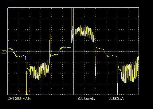
Here is a picture of the waveform I simulated in order to trip this breaker.
coilabattriplevels.jpg

This is a simulated arc signature as seen by the AFCI sensing coil. You are looking at a low voltage representation of the current in the line.

The purpose of this diagram is to highlight the individual components required in the signature to trip the breaker.

What I am presenting is a combination of what I have been able to derive from reading articles on the subject along with experimentation. I have no first hand knowledge of the firmware used in these devices.

This device contains four op-amp filter circuits that need to be satisfied for the parallel arc to be recognized as follows:

1) A minimum of 75 amps present in the 60 hz portion of the waveform.

2) You can see that the 60hz component of the current is ?chopped? near zero cross. This simulates the arc extinguishing and then re-establishing itself about zero cross. This satisfies the rapid di/dt requirement.

3 & 4 ) In the peaks you can see high frequency oscillations. These are a combination of ~35Khz and ~55Kz frequencies.

A further requirement that provides for enhanced immunity to false trips is that the high frequency content -must only appear- during the peaks and not during the zero cross.

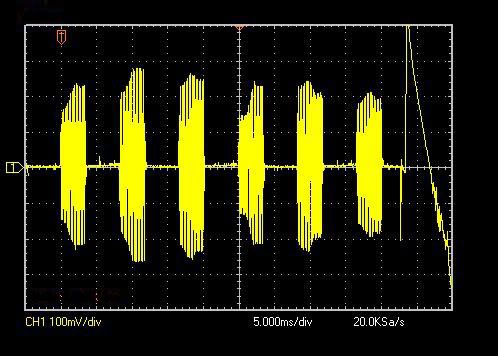
Below is a trace of one of the high frequency detection op-amp circuits outputs during an arc event. From this you can see that 6 half cycles was all that was required when presented with this simulated arc for the device to trip.
PIN8REDTRIPTIME.jpg

NOTE: I did not measure the time it takes for the trip solenoid to activate so it is possible that the 6th half ?cycle was not required to in order to recognize the arc.
 

iwire

Moderator
Staff member
Location
Massachusetts
Sorry about that Gar,
How is this?
AFCIs.jpg


I am not sure how much detail might be lost?

I replaced the large picture with a link and posted the smaller picture so your post will fit on peoples screens.

In general limit picture widths to 640 pixels or use a link. :smile:
 

ELA

Senior Member
Occupation
Electrical Test Engineer
Thanks for the update Bob!


I wanted to comment that this testing has given me confidence in this products immunity to false tripping. It took a lot of effort in order for me to simulate all of the requirements in order to have this breaker recognize the arc signature and trip.

As with any electronic product it is still possible for it to be "overpowered" by electrical interference at some level but I was impressed with the amount of effort I had to put into making it trip -due to an arc recognition.
 

gar

Senior Member
Location
Ann Arbor, Michigan
Occupation
EE
090309-0901 EST

Thanks ELA and iwire.

I have found that 640 is adequate for most purposes. When I take pictures at 2560 as compare to 640 I do not generally see any great improvement in information about fine detail. I suspect the primary problem is the compression algorithm used.

.
 

JKP

Member
How you simulated Series arc?

How you simulated Series arc?

Very Intresting...

I have the following questions

1)Could you simulate series arc at 120V 60Hz system to trip the SquareD make combination AFCIs?

2)What is the minimum load current required before arc generates?

3) Could you perform any trip time related tests?

4) How to perform parallel arcing conditions to test AFCIs?
 
Status
Not open for further replies.
Top