- Location
- Illinois
- Occupation
- retired electrician
gar,
Thanks...that is a very good way to explain it.
Thanks...that is a very good way to explain it.


Double-checking your work for fun:...Reducing this to its equivalent, I got...
Thus, there is a potential difference between the CNC chassis and the computer chassis equal to the voltage drop on the CNC EGC.
Even if you cut the neutral and then somehow put your body in between the neutral wire from the load and the other side of the cut neutral wire returning to the source, you would still have 120V across your body, because your body would now be in series with the load and current would return in series on the neutral with the voltage across you body being determined again by a voltaeg divider?
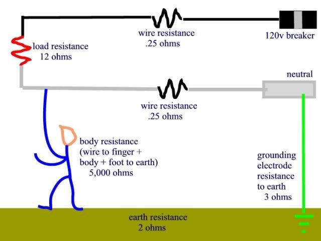
When I originally set this up, I took a reference from a study on resistance of the human body, under varying conditions of contact. Dry skin with contact of minimal pressure and surface area resulted in apparent resistance of around 10 K Ohms. However, the higher the pressure and the larger the contact surface area and the more electrolytes and moisture was present, the further the resistance dropped. Low readings of approximately 100 Ohms were observed.
For my hypothetical guy, working in soaked conditions on a job site at 3:30 on a Friday afternoon, I arbitrarily chose 500 Ohms for his through body resistance. I added another 500 Ohms for the footwear.
The wire resistance is simply from NEC Chapter Nine.
I left the open circuit source voltage at a low value.
This is the circuit diagram that I got.
Reducing this to its equivalent, I got:
That's pretty much the case as long as the neutral wire has a good connection back to complete the circuit.
It's also important to remember as soon at that connection is gone, the neutral wire becomes a "hot" wire.
I've seen a journeymen splicing neutral wires on live circuits. He didn't realize (and neither did I at the time) that as soon as he cut the neutral wire (to install a wire nut) that one of those ends suddenly had 120 Volts on it.
Steve
090730-1519 EST
philly:
Al provided a question earlier assuming 150 ft of #12 wire and 10 A thru the neutral. Effectively he asked what is the voltage drop on that neutral? Here is the answer --- 1000 ft of #12 copper is about 1.6 ohms, 150 ft is 0.24 ohms, 10 A and 0.24 ohms is 2.4 V. Under certain conditions 2.4 V can kill you.
To add to Al's last question. If your bare feet are on wet earth, your bare hands are holding the metal case of an electric drill, the extension cord is of most any length, all three wires in the cord are the same material and diameter, and there is a direct dead short between the hot wire and the drill housing, then the approximate peak voltage between your feet and hands is about 0.5*120*1.414 = 85 V. You will probably be dead.
Ok, we've discussed how there can be 120V on the end of a neutral that has been cut for a single branch circuit with only one load. I'm assuming that the same applies for a branch circuit with mutiple loads tied into a single neutral where you cut the neutral anywhere on the neutral wire.
Does the same principle apply for the neutral connected to multiple single phase circuits on a three phase system?
... the electrician had run out of cores ...
Al from your diagram above it looks like it shows the fault to ground happening on the neutral side of the drill load which I'm assuming is
"c". Since we are not breaking the neutral is this an example of my question from the origonal post, showing what happens when someone touches the neutral of a circuit that is still grounded?
This diagram doesn't look like the other case you talked about where the hot conductor made contact with the drill casing. Or am I missing something?
I had a discussion recently about what would happen if someone were to touch a neutral conductor (grounded neutral) that had current flowing through it.
I was thinking that because there is no voltage potential on the neutral in relationship to ground, there would be no new ground currnent introduced through the body. However because there is current flowing through the neutral your body would set up a current divider for this current with the neutral wire connected back to the source, and a small amount of current would go through your body. The amount of current would be dictated strictly by the amount of neutral current determined by upstream loads, and by the impedance ratio between your body and the neutral path returning back to the source.
Am I looking at this correctly?
Hi, Philly.I was thinking that the diagram was showing the neutral wire but it appears that it is showing the EGC wire, and "c" is where the Hot to EGC fault takes place. I see not that this is an EGC and how current can still go through the body even with an EGC.
I see not that this is an EGC and. . . .
Buckly,What is a 'core'?
")
Interesting. It's a new term to me, also.One of the wires in a Romex... must be another USA/elsewhere terminology thing