How does single-phase 240V look like when drawn out in a diagram, when there is only one attachment to line side of Xfmer, lets say 2400V? Are the two secondary legs out of phase with each other, how did it get that way with only one phase connected to primary?
You are using an out of date browser. It may not display this or other websites correctly.
You should upgrade or use an alternative browser.
You should upgrade or use an alternative browser.
Singlephase 240V
- Thread starter EEC
- Start date

- Status
- Not open for further replies.
Why assume two secondary legs?How does single-phase 240V look like when drawn out in a diagram, when there is only one attachment to line side of Xfmer, lets say 2400V? Are the two secondary legs out of phase with each other, how did it get that way with only one phase connected to primary?
gar
Senior Member
- Location
- Ann Arbor, Michigan
- Occupation
- EE
090830-1610 EST
On 480sparky's drawing put a dot at the top end of the top secondary winding. Then put a dot associated with the lower secondary at its end that connects to the center tap. This provides you with phasing information on the two coils.
When connected this way the two secondary coils add. If one of the coils was reversed, for example the the dot associated with the lower coil was at the bottom end of the lower coil, then the difference between the two hot leads would be zero volts or thereabouts.
.
LarryFine
Master Electrician Electric Contractor Richmond VA
- Location
- Henrico County, VA
- Occupation
- Electrical Contractor
EE, start with reading this: http://forums.mikeholt.com/showpost.php?p=708650&postcount=4
Then, come back and ask questions.
Then, come back and ask questions.
What transformer are you referring to?How does single-phase 240V look like when drawn out in a diagram, when there is only one attachment to line side of Xfmer, lets say 2400V? Are the two secondary legs out of phase with each other, how did it get that way with only one phase connected to primary?
There is no transformer which works with only one primary connection. Perhaps you are referring to a POCO pole-mounted transformer (POT; more specifically, a single-bushing POT ). On these there is only one LINE connection on top, but they are also connected to the distribution neutral on the side, which is also connected to the load side neutral.
What transformer are you referring to?
There is no transformer which works with only one primary connection. Perhaps you are referring to a POCO pole-mounted transformer (POT; more specifically, a single-bushing POT ). On these there is only one LINE connection on top, but they are also connected to the distribution neutral on the side, which is also connected to the load side neutral.
This is what I am asking about
SG-1
Senior Member
- Location
- Ware Shoals, South Carolina
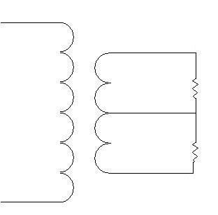
It could look something like this. This is part of a transformer nameplate, slightly modified. I connected 1 & 2 on the primary and added the ground connection on the primary.
How does single-phase 240V look like when drawn out in a diagram, when there is only one attachment to line side of Xfmer, lets say 2400V?
Note the 2400V is measured line to neutral/ground on the primary. It is actually 4160V line-to-line (that is, if there is a second or third line).
The secondary lines seem to be 180? out of phase because the voltage measurement is generally referenced to neutral. Yet, when voltage is referenced to either line, the neutral and other line measure in phase with each other, where the neutral measures at half the voltage magnitude as that of the other line.Are the two secondary legs out of phase with each other, how did it get that way with only one phase connected to primary?
SG-1
Senior Member
- Location
- Ware Shoals, South Carolina
Am I correct in assuming the primary is a corner grounded delta ?
Steve
Steve
gar
Senior Member
- Location
- Ann Arbor, Michigan
- Occupation
- EE
090902-1812 EST
SG-1:
No the primary is a Y and the primary neutral is shared with the secondary neutral. In many cases if you look at a pole it will appear that there is only one primary wire near the top and the primary neutral is intermixed with the secondary wires. But if you look far enough you will see the primary neutral wire continue on to the next transformer.
.
"Referenced to neutral"
"Referenced to neutral"
In Lay-men terms, what do you mean by referenced to neutral to get 180 degree out of phase?
"Referenced to neutral"
Note the 2400V is measured line to neutral/ground on the primary. It is actually 4160V line-to-line (that is, if there is a second or third line).
The secondary lines seem to be 180? out of phase because the voltage measurement is generally referenced to neutral. Yet, when voltage is referenced to either line, the neutral and other line measure in phase with each other, where the neutral measures at half the voltage magnitude as that of the other line.
In Lay-men terms, what do you mean by referenced to neutral to get 180 degree out of phase?
Because voltage is a measure of a difference in potential energy, it requires two points (contacts, connections, terminals) to make the measurement.In Lay-men terms, what do you mean by referenced to neutral to get 180 degree out of phase?
When I say reference the neutral, this would mean measuring the voltage to either line with one probe remaining on the neutral. When you move the other probe to the second line, you are reversing the polarity of the meter... so the voltage magnitude and phase appears reversed, compared to that of the first measurement.
gar
Senior Member
- Location
- Ann Arbor, Michigan
- Occupation
- EE
090902-2013 EST
EEC:
At my web site http://beta-a2.com/EE-photos.html
and at P5 --- Photo 2750A1 is shown a sine wave that was turned on at 90 deg. If without shifting the sine wave sideways but simply inverting the waveform you would have a waveform shifted 180 deg from the one shown.
Connect an oscilloscope common terminal to the neutral point and connect the channel 1 vertical probe to phase A and also synchronize the scope horizontal sweep to phase A. If a second channel is available, then connect this to phase B, and you will see the inverted sine wave on the second channel.
If only one channel is available use a separate probe to the sync input and maintain the sync from phase A. Move the vertical probe to phase B and you will see the inverted sine wave.
This results because the measurements are being made relative to the center tap (neutral) of the transformer, and the way the secondary windings are phased.
If you are working with full line voltage (120) and the center tap is grounded and connected to the EGC, then DO NOT connect the scope common to phase A or B. If you do, then you will get a big spark and something will burn up. If you run the test with a standard residential system vs a small isolated filament transformer, then do not connect the scope common to anything. Just let the scope use the EGC in its power cord to provide the common connection to the system neutral. Of course this does not allow you to use one of the hot lines as a reference.
If you use an isolated center tapped filament transformer as a test signal, then do not ground any output terminals, and connect the scope common to any point you want on the isolated secondary of the filament transformer.
.
cripple
Senior Member
- Location
- Santa Fe, New Mexico
Singlephase 240V
Utility distribution system is generally a grounded three phase wye system. The grounded conductor is carried with the three phases, and is grounded four times every mile.
Resident and small facilities are supplied by single phase power, one phase of a three phase system and the grounded conductor.
There utility distribution voltage system is 13.2KV, the residents the voltage to the grounded conductor is 7.6KV.
The residential voltage is 240/120 single phase stepped down from 7.6KV. The phase to phases voltage is 180 degrees out of phase and the phase to the grounded conductor is 90 degrees out of phase to each phase.
Perhaps 4x/mile where there are no service transformers closer together than that. AFAIK, it is connected to a grounding electrode at every service transformer.... The grounded conductor is carried with the three phases, and is grounded four times every mile.
Many are, but not all.... one phase of a three phase system and the grounded conductor.
Perhaps in some areas. Distribution voltages vary.There utility distribution voltage system is 13.2KV, the residents the voltage to the grounded conductor is 7.6KV. The residential voltage is 240/120 single phase stepped down from 7.6KV.
Your meaning is unclear to me...The phase to phases voltage is 180 degrees out of phase and the phase to the grounded conductor is 90 degrees out of phase to each phase.
"...phase to phases..."? On a 3? system, phase to phase voltages are 120? out of phase to each other. On 1? systems, there is no out of phase voltages.
"...180 degrees out of phase"? There is no such thing as 180? out of phase on common systems. At best, reversed polarity. On split phase systems, such as 120/240 1? 3W, where a transfomer winding is center tapped, or two equal windings are connected in series, and where this connection is used as a reference for voltage measurements, the two lines only appear to be 180? out of phase because you are reversing the polarity of the measuring device while taking the measurement. Instantaneous current flows in only one direction in this(these) winding(s).
"...the phase to the grounded conductor is 90 degrees out of phase to each phase"? Again, there is no out-of-phase voltages on a single phase system.
mivey
Senior Member
Out of phase with what? There is only one phase-phase voltage.The phase to phases voltage is 180 degrees out of phase.
The phase to neutral voltages can measured as 180 degrees out of phase with each other.
gar
Senior Member
- Location
- Ann Arbor, Michigan
- Occupation
- EE
090903-1648 EST
Smart $:
One can define the relationship of one sine wave to another where both are of the same frequency by the phase angle difference between them. This could be any value between - infinity to + infinity. Usually it is quantized to +/-2Pi or +/-360 deg. Certainly 180 is one of the possibilities. You can also describe the 180 deg phase shift as inverting the sine wave.
Truly a center tapped secondary provides two different phases that are 180 deg out of phase when the center tap is the reference point.
See dictionary.com for a definition of phase.
http://dictionary.reference.com/browse/phase
.
mivey
Senior Member
And what do you think would be different with two independent sources that were 180 degrees out of phase?Instantaneous current flows in only one direction in this(these) winding(s).
You and I agree. I don't know why this seems to be so confusing to many.090903-1648 EST
Smart $:
One can define the relationship of one sine wave to another where both are of the same frequency by the phase angle difference between them. This could be any value between - infinity to + infinity. Usually it is quantized to +/-2Pi or +/-360 deg. Certainly 180 is one of the possibilities. You can also describe the 180 deg phase shift as inverting the sine wave.
Truly a center tapped secondary provides two different phases that are 180 deg out of phase when the center tap is the reference point.
See dictionary.com for a definition of phase.
http://dictionary.reference.com/browse/phase
.
090903-1648 EST
Smart $:
One can define the relationship of one sine wave to another where both are of the same frequency by the phase angle difference between them. This could be any value between - infinity to + infinity. Usually it is quantized to +/-2Pi or +/-360 deg. Certainly 180 is one of the possibilities. You can also describe the 180 deg phase shift as inverting the sine wave.
Truly a center tapped secondary provides two different phases that are 180 deg out of phase when the center tap is the reference point.
See dictionary.com for a definition of phase.
http://dictionary.reference.com/browse/phase
.
Surely you guys are not going to sucker me into another discussion on this topic. You can call it anything you like, but if you are going to be technical, you must observe polarity in your measurements. The only way you can get an inverted or 180? out-of-phase waveform is to measure with polarity reversed. I am not trying to say this system cannot be utilized to effect the same result as a system with two distinct phases, 180? apart... but you cannot, within the terminological bounds of electrical power systems and distribution thereof, call the one under discussion a 2? system no matter how hard you try!!!And what do you think would be different with two independent sources that were 180 degrees out of phase?You and I agree. I don't know why this seems to be so confusing to many.

Last edited:
- Status
- Not open for further replies.