Now look at your exercise from the viewpoint of running 3/0 for the same circuit, but at a distance having the same resistance. That figures out to 232ft. Yet you are required to run a #6 for this circuit, too. Why do you not complain that a smaller grounding conductor is ok for this circuit?ok lets do it this way.
I did the calculations of the OP in this thread, with the given information
400' of 300Kcmil
400' of #6 EGC
going from the resistance table 8 in chapter 9 at 75?C resistance
300 Kcmil has a resistance of .01784 @400 feet
# 6 has a resistance of .204 @400 feet
this gives us a total fault circuit resistance of .22184
If the voltage from the ungrounded to the X0 is 120 volts you will have about 541 amps of fault current.
if the voltage from the ungrounded conductor to the X0 is 277 volts you will have about 1248.6 amps of fault current
if at 240 volts expect around 1081.8 amps
now every one of these will open a 150 amp breaker.
so why would we need a larger EGC other than the code says so.
The only time would be, if the panel with the breaker in it is also fed by a very long run and has feeders conductors close to the size of the circuit breaker feeding this circuit, like when we see a 200 amp panel feeding a 150 amp circuit, it might be a problem if the 200 amp has long feeders? this is why we need to have a PE stamp to say the #6 is ok
I just don't see it, and as Bob said in post 8 this code change was not made in the realm of safety. It was for the convenience of inspectors.
If I'm wrong in my caculations for a fault let me know
As mentioned by Bob Alexander, IIRC, not all fault are full bolted faults. Your exercise, is only covering that possibility. Did you consider the possibility and the affect on the operation of the breaker if the fault was not a full bolted fault? Would not a larger grounding conductor increase the liklihood a breaker will open on a less than full bolted fault?
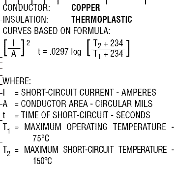
Additionally, this issue is also about affording protection to the conductors. At the instance a full bolted fault occurs, the temperature of the conductor rises. Upon exceeding the amperage at which the conductor is 75?C (the temperature at which you determined fault current), the resistance increases even more, so your calculated currents are not valid. I surmise the actual value is less than you calculated, but without researching the matter, I don't know the formula that will accurately calculate the amperage.
One issue that I do know which makes a difference is the fact that damage to 75?C thermoplastic-insulated conductors is considered to not occur until the conductor, during a fault, reaches a temperature of 150?C. Given that temperature is roughly, directly proportional to the ΔI? ratio, the current at which damage occurs is less than double the ampacity of the conductor. So the ocpd must open in time to keep the RMS fault current from reaching that value.

