Troubleshooting a voltage problem

Status
Not open for further replies.

UBG

Member
Location
So Cal
Occupation
Electrician
Greetings and thanks to all the smart and experienced electricians and engineers here in the forum...i'm an electrician with over 20 years of experience, and I feel like I should know the answer to this question already, so I'm a bit embarrassed to be having to ask....but I think its important to always keep learning. Here's the scenario:

A customer reported isolated power loss in her residence: two dimmers in the same 2-gang box suddenly stopped turning on their respective fixtures (one an interior chandelier and the other an exterior sconce). Wiring method in this particular switch box is NMC. She reports all other power and light to be functioning normally. Service is 120/240v 1P 3W, located in Los Angeles. All breakers are located in the service, there are no subpanels. I did not open the dead-front of that panel on the day I was there, due to heavy rain.

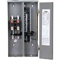
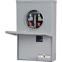
Testing the voltage on the hot that feeds both dimmers, the meter initially read 95 volts, hot-to-neutral and hot-to-ground. Neutral-to-ground voltage is zero. It then suddenly and abruptly dropped to 75 volts for no apparent reason. In the process of reseting all branch circuit breakers in the panel, one at a time, (none were labeled), I discover that turning one particular breaker off drops the voltage on the "problem" hot to zero, AND, turning off the ADJACENT breaker in the panel, while the problem circuit is energized, actually restores voltage on the problem circuit to normal. Although I did not open the dead-front and check the voltage at the breaker wire lugs, the breakers in question are full size and mounted in the relatively new panel in the same way that a full sized 2 pole breaker would be, likely having 240V potential between their respective loads.

No other loads in the house (at least none that are both known AND accessible) seem to be connected to EITHER of these two breakers. As a side note, in addition to the lack of adequate labeling, there are other indicators that a non-professional modified the wiring in this small house: missing NMC connectors, poorly mounted j-boxes, etc., so I'm not too surprised that these two lighting outlets seem to be the ONLY loads on one 20A breaker, and that at least one OTHER breaker has little, if any, load connected to it at all.

I suspect that some type of short circuit condition is the cause of the low voltage reading, and that the short was cleared by shutting off the second breaker....but I feel like I should be able to tell more about the type of short from the information that I have described. Is it line to line? Or line to ground/neutral in a combination circuit?

I left the second breaker off, and advised my client not to turn it back on unless and until further troubleshooting was done to discover and correct the true cause of the problem, even if turning it back on did not SEEM to have an impact on the lighting circuit in the same way that it was while I was there.

Thanks in advance for your time and input, and I'll try to answer any questions you might have about any details that I have not covered in the description above.
 
Try troubleshooting it with wiggys and not a digital meter.

I am willing to bet that 95 volts is 'phantom voltage'

Read this BULLETIN

Thanks iwire. I'm a little familiar with phantom voltage, and notice them all the time...I did not know that high impedance testers were particularly prone to picking that up, and that bulletin is an nice concise explanation, so thanks for the link.

I did test with wiggy; the wiggy indicated voltage was present; not enough to move the needle, but enough to get it humming...about what I would expect from 75-95 volts, so with respect I don't think thats the answer. I also cant see how that could account for the voltage on that wire being restored to normal when the adjacent breaker is turned OFF
 
"Is it line to line? Or line to ground/neutral in a combination circuit? "

Seems to me to be a decent guess. As long as the voltages on the rest of the circuits remain stable, you evidently have some cross wiring between these two circuits. I would check the panel voltages first.

With a stable neutral connection, it would take a good load to drop the voltage. Take some amp readings.

Maybe they are sharing a compromised neutral.

Got a circuit tracer?
 
[ultiwire circuit.[/QUOTE]
Thanks Don; yes that makes sense to me too...

Maybe they are sharing a compromised neutral.

Got a circuit tracer?

Thanks mivey...The more I think about it, the more likely it is this, as opposed to your thought about load related voltage drop..

If the neutral was completely open somewhere between the switchbox where I took the voltage readings and the panel, AND the ground was good all the way back, I would expect to read SOME voltage between that neutral and ground...am I wrong?

The neutral could also be just LOOSE somewhere, but if that was the case, would it be expected that the light fixtures resumed working (as they did) when the second breaker was shut off?

I had a similar problem which was a bad connection on the neutral on pocos side
AV, thanks, I'm not familiar with the word "pocos"...does it mean POwer COmpany?
 
Is there any way that another feed is coming into one of the lights. Seeing as they are dimmer switches they could be the cause of the lowered voltage reading. A separate feed to the lights could have overloaded the switches or the switches could have gone bad. Had it happen to 15 amp 3 way switches on a 20 amp track lighting job. Shutting off the extra feed at the breaker restores proper voltage to the lights. Hard to come up with ideas without seeing the system.
 
Is there any way that another feed is coming into one of the lights. Seeing as they are dimmer switches they could be the cause of the lowered voltage reading. A separate feed to the lights could have overloaded the switches or the switches could have gone bad. Had it happen to 15 amp 3 way switches on a 20 amp track lighting job. Shutting off the extra feed at the breaker restores proper voltage to the lights. Hard to come up with ideas without seeing the system.

Thanks agermeyer. The voltage measurements were taken ahead of the dimmers (dimmers disconnected from the hot) not on the load side of the dimmer. Only the switchleg, neutral and ground are brought to the respective fixtures...the hot is only present in the switch box. Dimmers functioned normally once 120v was "restored" by shutting OFF the second breaker.
 
Absolutely. The two breakers that affect the voltage share a neutral.

Thanks Larry, yes, I know what a multiwire circuit is.

I'm hoping to find here some guidance toward WHY the readings I took are what they are...this is where my knowledge of theory gets weak:

In a multiwire circuit, several different problems could occur:
  • a completely open neutral,
  • a neutral that is not completely open but is connected so loosely that it creates a resistance (maybe impedance is the more appropriate word?),
  • a high-resistance short between the two hots (very little current flow hence no tripped breakers)
  • and probably others I have not mentioned.
I know that in the case of an open neutral on a MW circuit, the location that the problem happens at, relative to the loads that are connected to it, as well as the impedance of the connected loads themselves, affects which of the connected loads see voltage below 120, and which ones see voltage that is btw 120 and 240. This can be calculated (i think?:-?), but I just never learned exactly how...
 
100121-0834 EST

ron m:

First, can you explain what the reasoning is in your area to place main panel and breakers outdoors exposed to rain?

Assume that it is raining out, and the news here says it is very heavy today, then consider what can be done without opening the panel.

At your box with the dimmers disconnect the supply side hot wires from both dimmers.

Use a high impedance meter, like Fluke 27 or 87. Also have a 100 W incandescent bulb and a 1500 W heater for loads.

Assuming that the water system is copper, connected to the grounding electrode, and that neutral is also connected to these two (bonded in your terminology), then attach a long test lead from a water pipe near its entry to the house. This will be a reference point for voltage measurements.

If the water system is not copper, then put a screwdriver in the outside earth as your reference point. If there is good grounding and no excessive current to the grounding system, then I do not expect there to be more than maybe 200 MV from the screwdriver reference to any other item that is supposed to be grounded so long as no current is flowing to said other item.

With both breakers on measure the voltage from said ground reference to your dimmer hot and neutral leads. Should be near 120, and 0. While continuing to monitoring the voltage hot to the ground reference apply the 100 W load between hot and its neutral. What is the voltage? Then the 1500 W. Record these voltages. Might do the same tests measuring neutral to the ground reference.

Repeat with the other combinations of the two breakers. That is three more conditions. Breaker A on and B off, B on and A off, and both off.

The results will determine what to do next. 100 W at 120 V is about 0.83 A, and 144 ohms. 1500 W at 120 is about 12.5 A, and 9.6 ohms.

.
 
100121-0834 EST

First, can you explain what the reasoning is in your area to place main panel and breakers outdoors exposed to rain?

I'm sure other (older? haha) electricians from So Cal might be more qualified to answer this, but...Back in the 1920's, maybe even the '30's, stand-alone meter sockets, installed adjacent to or separately from OCPD's were common...I have seen many old meter sockets from that era even installed INDOORS (obviously not ideal for the meter reader).

I can only guess at the reason, (I'm thinking it's because weather is rarely a serious consideration here) but most single-family dwellings throughout So Cal use a meter-breaker combination similar to these; this began to happen, I'm guessing, in the 30's, and was standard by the post-war building boom of the 40's.
6293914.jpg
2438562.jpg


Assume that it is raining out, and the news here says it is very heavy today, then consider what can be done without opening the panel.

At your box with the dimmers disconnect the supply side hot wires from both dimmers.

Use a high impedance meter, like Fluke 27 or 87. Also have a 100 W incandescent bulb and a 1500 W heater for loads.

Assuming that the water system is copper, connected to the grounding electrode, and that neutral is also connected to these two (bonded in your terminology), then attach a long test lead from a water pipe near its entry to the house. This will be a reference point for voltage measurements.

If the water system is not copper, then put a screwdriver in the outside earth as your reference point. If there is good grounding and no excessive current to the grounding system, then I do not expect there to be more than maybe 200 MV from the screwdriver reference to any other item that is supposed to be grounded so long as no current is flowing to said other item.

With both breakers on measure the voltage from said ground reference to your dimmer hot and neutral leads. Should be near 120, and 0. While continuing to monitoring the voltage hot to the ground reference apply the 100 W load between hot and its neutral. What is the voltage? Then the 1500 W. Record these voltages. Might do the same tests measuring neutral to the ground reference.

Repeat with the other combinations of the two breakers. That is three more conditions. Breaker A on and B off, B on and A off, and both off.

The results will determine what to do next. 100 W at 120 V is about 0.83 A, and 144 ohms. 1500 W at 120 is about 12.5 A, and 9.6 ohms.

GREAT suggestion, just the type of stuff I'm looking for here :D THANK YOU!
 
check neutral on neutral bar, also check for continuity between neutral and ground, OHMS should be zero. if a local handy man/ "lectrician" just "helped out". when you open the panel check all connections for tightness and visible heat damage. additionally, correct wire size on corresponding breaker. In So. Oregon most homes have panels out side as well.
 
Status
Not open for further replies.
Top