3-phase transformers

Status
Not open for further replies.
Cold Fusion:


Here is an older Schematic I have posted at ECN, which describes the Open Delta TEE, with 120/208V 3 Phase 4 Wire Secondary:
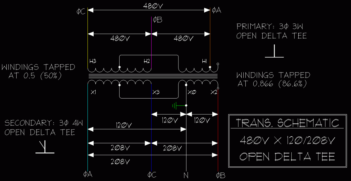
185.gif


Sorry, no Vector Diagrams available...

...
I've seen one of these -- although probably no more than one. Just never heard of it described as "open delta". Interesting. I wonder what there is about this that would be considered "delta"? No need to answer - just a rethorical question.

cf
 
100127-2344 EST

Without further information on the design of the transformer there is a problem with the implication of a common magnetic core. There will be severe circulating currents.

.

.
 
The confusion often lies in the explanation of a single phase service being 180 deg out of phase. The real reason the 180 exists is because of the center tap as if you had two 1.5 volt batteries in series. You are simply reversing the leads. It makes a difference the polarity of the test leads. Centertap IE ground the point between the 2 batteries and you will get +1.5v and -1.5v where if you went end to end you would get +_ 3 volts. I hope this helps.
 
100127-2344 EST

Without further information on the design of the transformer there is a problem with the implication of a common magnetic core. There will be severe circulating currents.
gar -
If you are discussing the 3ph tee xfm, The one I saw was maybe 10kva, about half the size of a breadbox, and ran so hot you didn't want to be in the same room with it.

cf
 
gar -
If you are discussing the 3ph tee xfm, The one I saw was maybe 10kva, about half the size of a breadbox, and ran so hot you didn't want to be in the same room with it.

cf
Most of the commercially available 3-phase 'encapsulated' transformers 15kVA and smaller are built as T connected units. This has been the standard practice for several decades.
 
100128-2151 EST

Cold Fusion:

The circuit I was referring to is the last drawing labeled "Open Delta Tee". The implication I see is that all three primaries (or one center tapped primary and one untapped primary) are on the same core. So assume it is a toroid these two or three windings are on to easily see the magnetic path.

The single winding has an induced voltage from the center tapped winding that is in phase with the center tapped winding. But the applied voltage from phase A to CT is 90 deg shifted from the B-C phase. Thus, a conflict.

Two transformers or some other magnetic circuit would solve the problem. But I do not believe that is implied by the schematic.

Is there some trick implied by the schematic, or something I do not understand about the fields?

.
 
Last year we had a 150kva 480 X 208Y/120v 3 phase 4 wire dry type transformer which had phase C catch on fire, tripped supply breaker,etc., this transformer was feeding all single phase loads, had to disconnect the phase C and reroute 2 wires the best that I remember ( WOULD HAVE TO LOOK AT A TRANSFORMER TO TELL YOU THE EXACT WIRES WHICH I RELOCATED ) to balance out voltage, current, etc., did not have enough spaces in the existing panel to connect everything on A and B phases, added a 1 phase temporary panel to the side and moved circuits over to it, customer used this way for 6 days until we could get another transformer and install, manufacturer decided it was a faulty unit, we tried to just remove phase C from the picture with out rerouting any wires but this would not work
 
In my post #46 the first paragraph is scrambled at the end. It should have read something like the following:

The circuit I was referring to is the last drawing labeled "Open Delta Tee". The implication I see is that all three primaries (or one center tapped primary and one untapped primary) are on the same core.

So assume this core is a toroid, then it is easy to see that the same magnetic flux links all of the coils on this single magnetic path.

.
 
How true:

How true:

In my post #46 the first paragraph is scrambled at the end. It should have read something like the following:

The circuit I was referring to is the last drawing labeled "Open Delta Tee". The implication I see is that all three primaries (or one center tapped primary and one untapped primary) are on the same core.

So assume this core is a toroid, then it is easy to see that the same magnetic flux links all of the coils on this single magnetic path.

.

It appears that the draftsman erred in drawing a single core for the two transformers. This "T" connection transforms 2-ph to 3-ph or vice-versa. One could use this to drive a 2-ph motor for example--if one could find one.
 
Status
Not open for further replies.
Top