PQ Scope Picture & Question

Status
Not open for further replies.

iwire

Moderator
Staff member
Location
Massachusetts
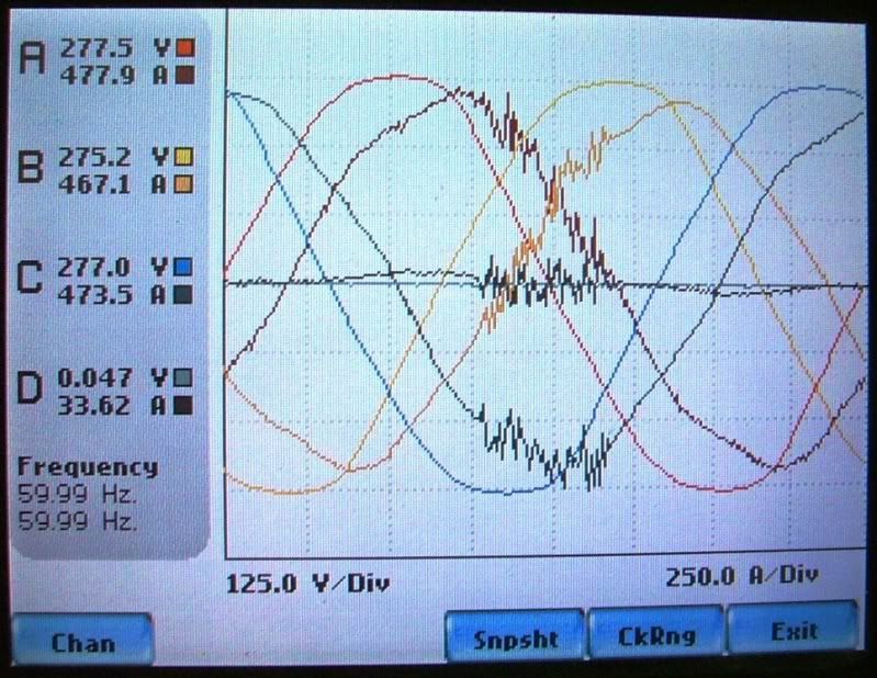
I have a customer that asked me to look into an increase of 4% in their electric usage. So for the heck of it I put our PQ meter on the service and I saw a wave form I have not seen before.

A lot of current 'noise' on all thee phases and neutral during only one part of each cycle.

Can anyone identify what might be going on and if it may be effecting the KWH usage?


PX5PQRB1.jpg
 

K8MHZ

Senior Member
Location
Michigan. It's a beautiful peninsula, I've looked
Occupation
Electrician
Would it be possible to 'zoom out' a bit in order to see if there is a pattern?

Also, can you take some readings at the 3 phase loads, looking for one that may be pulling around 33 amps?

Are there any 3 phase induction furnaces on the premises?

Looking a bit closer, how about checking single phase loads on C with a compromised neutral? Note that the skewing is centered around the current peak of phase C.

I also see a current lag there. Cause, or effect???
 
Last edited:

K8MHZ

Senior Member
Location
Michigan. It's a beautiful peninsula, I've looked
Occupation
Electrician
Another thing I noticed that may indicate a problem on trace 'A'.

Looking closer, it may be a bad cap on phase A, not C.

Note that the interference starts at the peak of trace 'A' and stops exactly as it crosses the zero line?

My spidey senses tell me this is a reactance problem.


OK, I am done guessing. I hope I helped more than I hindered.
 
Last edited:

mivey

Senior Member
Those are some great guesses K8. It definitely looks like noise tied to something like you mentioned or switching or pf correction or even some arcing. If it was arcing, I would think a 4% increase in usage would have shown up as a heat source already. Maybe the 4% is not all due to this anomaly.

Iwire, does it occur in the same place on the waveform every time and for the same duration?
 

mivey

Senior Member
As far as I can tell yes.

The meter is still there recording unfortunately I do not have remote read capabilities.
If it is a precise re-occurrence, it would almost have to be some switching device kicking in like some motor controller or pf correction type equipment. I can't imagine an arc or similar failure being so precise.
 

iwire

Moderator
Staff member
Location
Massachusetts
If it is a precise re-occurrence, it would almost have to be some switching device kicking in like some motor controller or pf correction type equipment. I can't imagine an arc or similar failure being so precise.

Possible VFD acting badly?
 

mivey

Senior Member
I wonder why the voltage seems unaffected? You don't think the meter leads might be picking up noise do you?
 

steve66

Senior Member
Location
Illinois
Occupation
Engineer
I think the odd thing is that is occurs on all three phases and the neutral at the same time. Not at 120 deg. apart like you would expect to see from any three phase loads.

And the other interesting thing, of course, is that it only occurs for part of the wave.

And it is a huge current: a couple hundred amps. But it seems to have no effect at all on the voltage. That makes me wonder if it is real.

Just a guess: Maybe this signal isn't on the wires at all. Maybe it is just radiated from a radio or something like that. Similar to a ghost voltage, but picked up in the wires between the current probes and the meter.

Are there any radio's or TV's or CRT's nearby??
 

steve66

Senior Member
Location
Illinois
Occupation
Engineer
Mivey was thinking the same thing, but beat me too it.

It will be interesting to see if we are right.
 

iwire

Moderator
Staff member
Location
Massachusetts
Just a guess: Maybe this signal isn't on the wires at all. Maybe it is just radiated from a radio or something like that. Similar to a ghost voltage, but picked up in the wires between the current probes and the meter.

Are there any radio's or TV's or CRT's nearby??

Nothing odd that I remember, the entire meter was inside the metal enclosure of the main switch gear, there is a pringle switch with GFP controls and CT metering in the same section of gear that the meter is in.

Maybe it is not real, but I have never seen that pattern before with this meter.
 

mivey

Senior Member
As the A phase current approaches the peak, the neutral current starts to rise. At the peak, it all falls apart. This does not happen with B & C phase, although they are involved once it goes south.

Maybe a bad MOV, SPD, or arrestor and phase A?
 

mivey

Senior Member
As the A phase current approaches the peak, the neutral current starts to rise. At the peak, it all falls apart. This does not happen with B & C phase, although they are involved once it goes south.

Maybe a bad MOV, SPD, or arrestor and phase A?
It started to on the negative swing but did not quite reach the threshold. A slight DC bias perhaps?
 

mivey

Senior Member
It started to on the negative swing but did not quite reach the threshold. A slight DC bias perhaps?
I estimate the neutral reached 63 amps on the positive 1/2 cycle and about 38 amps on the negative 1/2 cycle.

Now, why would the A current drop as the neutral current increases?

add: That much current shunting could eat up some energy over time.
 

Besoeker

Senior Member
Location
UK
And it is a huge current: a couple hundred amps. But it seems to have no effect at all on the voltage. That makes me wonder if it is real.
[/QUOTE]
I wondered about that too. The fundamental current lags the voltage by maybe around 40 deg which means loading is overall inductive.
Yet the current shows a burst of oscillation in the region of a few kHz in all phases and neutral at the same time. You'd think that getting such a current to flow in a predominantly inductive load would show some at least some reflection on the voltages.
Interesting too, that the currents are very balanced. Maybe iwire, if you are reading this, you could give some information on the connected loads?
 
Status
Not open for further replies.
Top