You are using an out of date browser. It may not display this or other websites correctly.
You should upgrade or use an alternative browser.
You should upgrade or use an alternative browser.
Grounding Grid
- Thread starter Pushpin
- Start date
- Status
- Not open for further replies.
zog
Senior Member
- Location
- Charlotte, NC
Does anyone have a drawing of a grounding grid for a Bulk Storage Facility that I could use for a pattern?
Thanks
Pushpin
Don't you have a spec to follow? Grids need to be engineered to meet the specs provided.
- Location
- Illinois
- Occupation
- retired electrician
What is the purpose of this grounding system?
ohmhead
Senior Member
- Location
- ORLANDO FLA
Heres one
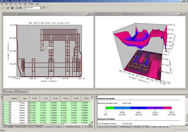
Now all you need is the program to design it .
Now all you need is the program to design it .
kingpb
Senior Member
- Location
- SE USA as far as you can go
- Occupation
- Engineer, Registered
I'm doing the design. No specs yet. I'm thinking 4/0 run with 2/0 taps to motors, pipe supports, tanks ect. I've seen it done so many ways not sure what's right.
I'm not sure how many ground wells would be needed and how far appart.:-?
What is right is the correct amount of copper to reduce the step and touch potentials to safe levels.
My recommendation would be you hire a testing company to go get the resistivity values and various points, meanwhile start reading IEEE 142 and IEEE 80 before attempting any design. Then purchase a good program, then be able to accurately interpret the results, i.e. bad info in, is bad info out.
- Location
- Illinois
- Occupation
- retired electrician
Is that an issue in a typical industrial type installation where the voltage is less than 600 volts? I thought that was normally only looked at for medium voltage switch yards and things like that.What is right is the correct amount of copper to reduce the step and touch potentials to safe levels.
I don't recall any grounding for step and touch potential in any of the tank farms I have worked on. Most had the circuit EGC and a ground grid of 4/0 with electrodes every 200' or so around the perimeter and two 2/0 tails to each major structure.
kingpb
Senior Member
- Location
- SE USA as far as you can go
- Occupation
- Engineer, Registered
Step and touch potentials are always a concern. Yes, as you know different installations require different means and methods. But even a light pole in the vicinty of power lines can give you a good shock if not grounded properly.
Sounds like the ground you are describing is more for dissipation of lightning protection. But either way you are building a ground grid (ring in this case). By placing it around the tank you are in essence covering touch potentials. Could be if you do the calcs that step potentials are probalby not a concern. But without doing a ground calc how do you know the design is good enough for touch potential either.
Same principle as installing a ground conductor around the perimeter of a building 3' away. Takes care of touch potentials; i.e. arm is not going to reach more than 3' or so.
In many instances grounding design seems to be like vodoo magic.
Last edited:
- Location
- Illinois
- Occupation
- retired electrician
King,
I guess my real question is if these types of grounding grids are really being designed and installed to limit step or touch potential? Other than switchyards or substations, and special cases like those covered in Article 680, I don't hear much about grounding grids being installed for that purpose.
It is my understanding that the intent in most electrical installations, other than those very high power installations like substations, if for the EGC to carry enough current so the the OCPD opens the circuit in a very short time. Of course for the time it takes the OCPD to open the circuit there many very well be a harzardous step or touch potetntial, even on 120 volt circuits.
- Status
- Not open for further replies.