GFCIs on 2 Wire Residential Branch Circuits

Status
Not open for further replies.

bilwei

Member
Location
Lufkin, Texas
RE: Article 406.3 (D) (3)

We have installed GFCI receptacles to replace non-grounding-type several times in recent years. In a recent installation, we tested the GFCI receptacles with an Ideal 61-165 Sure Test Circuit Analyzer. The (new) GFCI Receptacles would not trip. We tried an old Woodhead LED type tester with a GFCI trip button and they did not trip. We called the local AHJ for input. They said to bond the grounded conductor to the ground screw on the GFCI receptacle. They said this would be acceptable and the GFCI receptacle did trip with both Testers. No mention of this bonding in the code book that I can find. I have safety concerns with past installations at this point and same with this bonding solution. ( I don't know test results of past installations because it has been awhile since we have encountered this type of installation)

We conducted our own real world unscientific test (with all appropriate PPE).
Test #1 - plugged an extension cord into a new GFCI receptacle and dropped the other end in a bucket of water. Result - did not trip???
Test #2 - connected a control relay to the extention cord and dropped in a bucket of water. Result - did not trip??

Bonded the grounded conductor to the ground screw on the GFCI receptacle and repeated both test. Result - GFCI receptacle Tripped

What say yee?
 
I cannot even begin to believe the AHJ allowed this, let alone actually suggested it. It is dangerous, and it is a violation of the NEC because it is dangerous.

I urge you to undo this wiring error at your earliest opportunity!

Code reference is 250.24(A)(5).

The only valid way to test a GFCI receptacle that is connected without an EGC is to push the test button. Any external tester will attempt the test by creating a short to the EGC. But since there is no EGC, the tester will not be able to cause the receptacle to trip. That is a weakness in the test process, and has nothing to do with the ability of the receptacle to do its job.
 
A plug-in GFCI tester will NEVER work on an ungrounded GFCI receptacle.

As Charlie mentioned, the ONLY was to properly test a GFCI is to use the built-in test button. This is a UL standard.

And, as Charlie also mentioned, you have created a very serious hazard doing what you did, even with the inspectors' say-so.

Undo it all and use the built-in test buttons.
 
We conducted our own real world unscientific test (with all appropriate PPE).
And it appears to me that you drew the wrong conclusions from it.


A GFCI will trip when it sees current flowing in the phase conductor, without seeing an equal amount of current flowing in the grounded (neutral) conductor. In both your test setups, you created a situation in which current would be able to flow from the hot to the neutral, via the bucket of water, without allowing any additional stray current to flow from the hot conductor to planet earth. As long as the GFCI device sees the same current in both wires, it will think that everything is normal. When you bonded the grounded to the grounding terminal on the receptacle, you created another path for current flow, making the hot and neutral currents no longer equal. Without seeing your set up, I cannot say exactly what that additional path might have been. I don?t know if you did this on your garage bench, or in a real house that has EMT conduit being used as an EGC path. All I can say is that the GFCI saw a difference in current, and that is its criteria for tripping.
 
There's a wee bit of confusion here ...

UL doesn not list AFCI 'testers,' just 'indicators.'

UL most certainly DOES list GFCI 'testers.' Testing a GFCI with a plug-in tester is a perfectly acceptable means of testing a GFCI. This is NOT the case with AFCI's.

Why? Because a GFCI tester can create a simple current imbalance using the ground wire. For AFCI's, however, the specific arc forms are not specified by the tests, so every manufacturer has his own "standard." For GFCI's, 5-mA of leakage is 5-mA, no matter how the device operates.

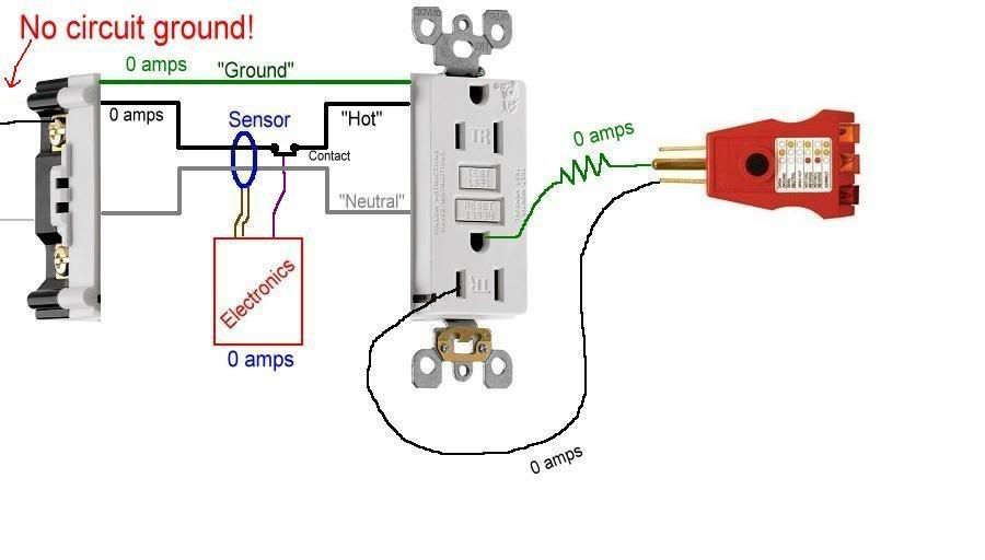
For the tester to work, the current needs to have somewherre to go. Without a ground wire, there is no way for the tester to work.

In that instance, then the test button on the GFCI is the only way to test them, as they can divert some current inside the device, and by-pass the GFCI circuitry.

So, if there is no ground wire present, the plug-in tester cannot work - but the GFI can still do its' job.
 
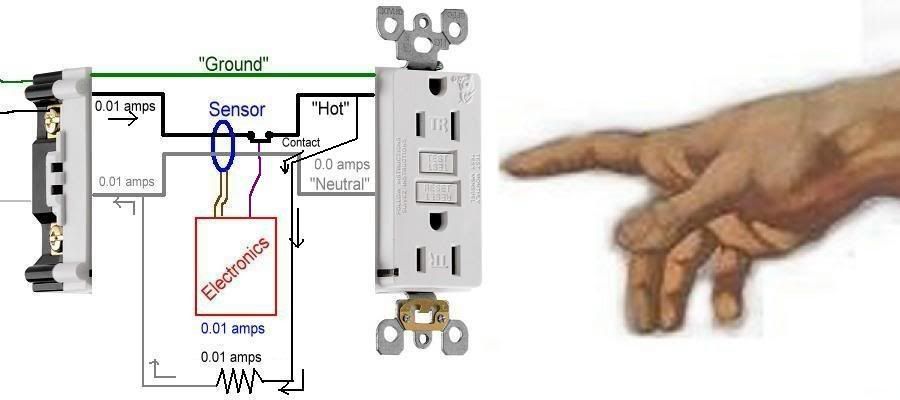
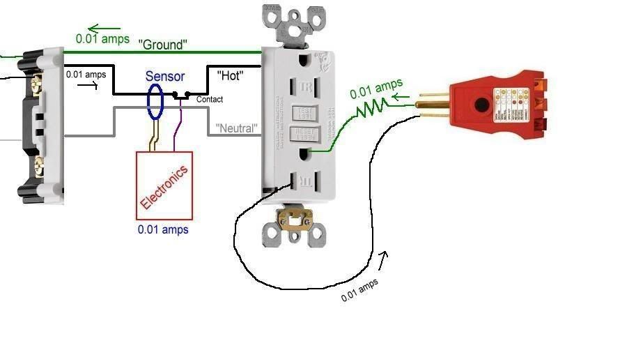
OK, I did a little drawing on some of my graphics software, and I hope this thread will help you (all) understand what a GFCI does, how it works, what role the ground wire plays, and why a plug-in tester won't make one trip if there's no ground.​


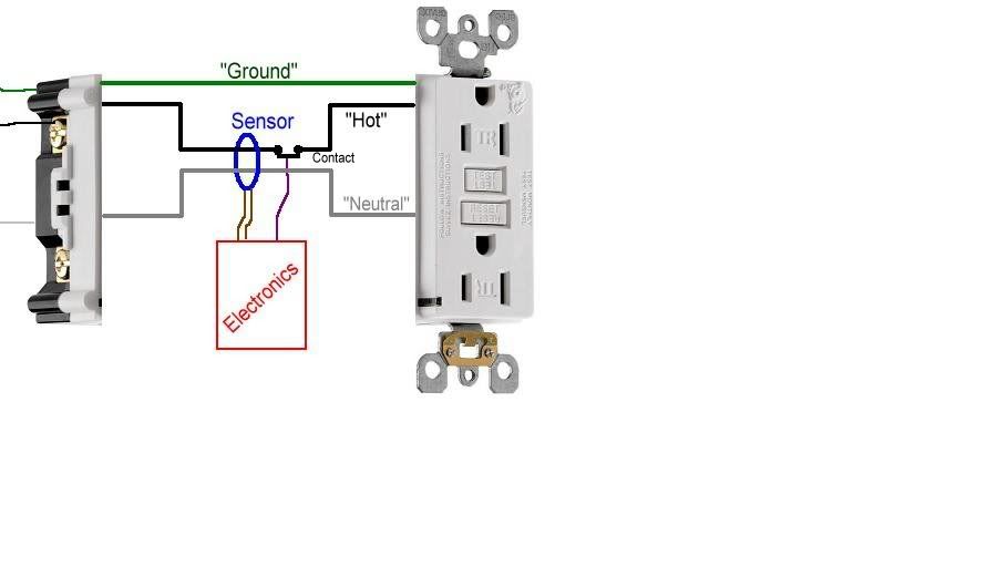
Let's take a standard GFCI receptacle and take it apart. Inside you will find an electronics board (an IC to some of you), a sensor, and a contact. Since the innards of an actual GFCI are quite complicated, I'll use my crude drawing to make things (hopefully) a little more clear.

GFCI1.jpg


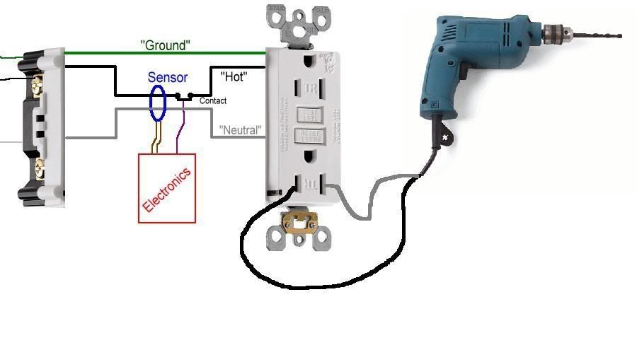
Now, let's plug in a power tool, with the assumption that the tool is safe to use.​

GFCI2.jpg


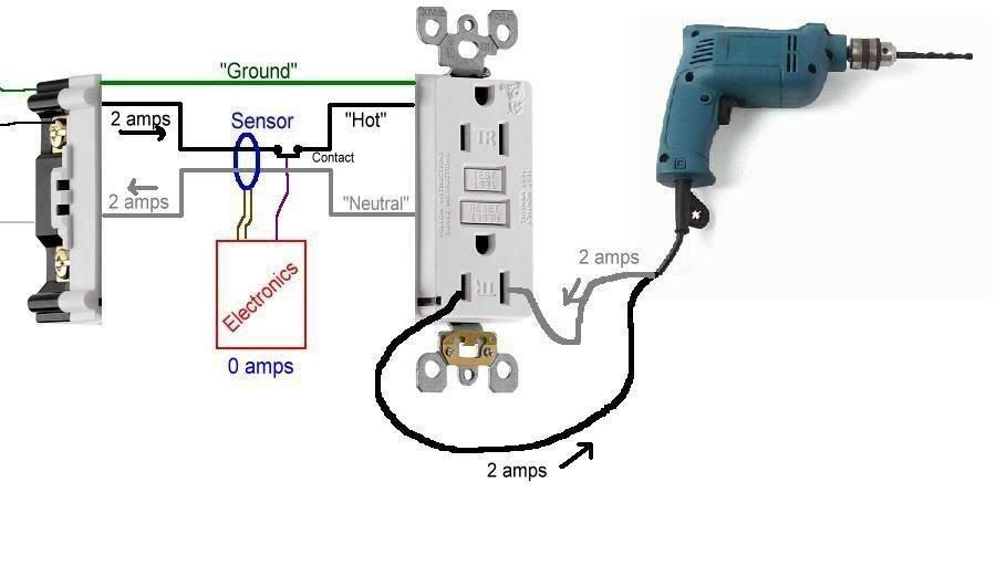
When you turn the drill on, it draws current through the entire ciruit.... the 'hot' and 'neutral' conductors both have the same amount of current flowing through them, only in opposite directions.​

GFCI5.jpg

Since the same amount of current is flowing through both the hot and neutral, they will cancel each other out and the sensor will detect 0.0 amps. If this sensor detects more than 0.005 amps (5mA), then the electronics picks this up and will open the contact, turning power off to the outlet.​

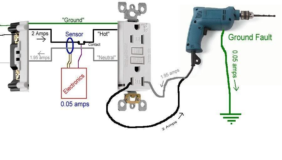
So let's do just that. Let's say there's a problem with the cord or the metal case of the drill (yea, I know, the drill looks like it's plastic, but let's pretend it's metal), and a ground fault exists between it and a ground. Now, current will flow through the hot, and to the ground fault. Let's say the fault current is 0.05 amps.​

GFCI6.jpg

The drill will still run properly, but part of the current it consumes does not return through the proper path (the neutral). Instead, it flows through the ground fault.​

The sensor will detect an imbalance of 0.05 amps, and the electronics will open the contact and turn of the power.​

This is the primary and sole function of GFCI protection. It is assumed a ground fault is going through a human being and turn the power off. Only when the fault is removed will the ability to restore power with the 'Reset' button work. The GFCI does not care whether there actually is a human getting shocked or not. It could be the end of a cord is lying in a puddle of water. It could be a fault the operator of the drill is not a part of. Nonetheless, once more than 0.005 amps flows through a ground fault, the GFCI opens.​

Now, in order to test a GFCI receptacle, the manufacturers put in a handy-dandy Test button. What this test button does is create a small current flow (using a resistor to simulate a load with a ground fault) that intentionally bypasses part of the sensor, forcing it to sense that imbalance. If the GFCI sensor, contact, and electronics are functioning properly the power will be shut off.​

GFCI7.jpg


Now, up until this point, you will notice the 'Ground' wire has not been mentioned, nor has any current flowed along it. Point is, none needs to. The ground wire is there to open the breaker or fuse if there is a fault within the wiring beyond the receptacle. If the drill was shorted internally, then the ground would carry enough current to cause the breaker or fuse to open and turn off the power. The ground wire is for the operation of the breaker or fuse, NOT the GFCI. If no ground wire existed to feed this receptacle, the GFCI will still function as designed...... sensing imbalances and turning power off in a ground-fault situation.​

The only function a ground wire has in the operation of a GFCI is when a plug-in tester is used to test a GFCI. One important note here; the industry standard is to use only the built-in Test button to check for proper function. UL does not recognize using plug-in testers as a proper method of testing GFCIs.

GFCI8.jpg


With a properly-wired (3-wire) GFCI receptacle, the only way a plug-in tester can safely simulate an imbalance is to induce it through the ground. It has to, since it cannot bypass the sensor using the neutral. If you placed the resistor between the hot and neutral, the GFCI would only 'see' it as any other load, as the current flow between the hot and neutral would be equal and cancel each other out at the sensor.​

With the plug-in tester, the current flows out through the hot, and back through the ground. Since current flow on the ground is not going through the sensor, only the current on the hot is detected. With no opposing return current flow to balance it out, the electronics assume a ground fault and opens the contact... turning power off.​


If you only have a 2-wire (ungrounded) circuit, then the plug-in tester cannot create a current flow on the ground as the ground is not there. Since no current can flow in this incomplete circuit, the GFCI will sense 0.0 flow and not open the contact.​

GFCI9.jpg


There are other things today's GFCIs do that are not relevant to the discussion here, but I'll mention them here.​

One is Loss of Neutral. The electronics can sense the loss of the circuit's neutral, and will open the contact. The reason being, if there is no neutral, the electronics cannot fuction in order to open the contact in the event of a ground fault. So if the neutral feeding the circuit opens, the GFCI will turn the power off.​

Another is a self-test function. If the internal wiring of the GFCI becomes damaged (either physically or, say, a surge due to lighting), the power will shut off as well. Pushing the Reset button will not reset it.... it will stay off and need to be replaced.​

Another important function is Line-Load and Hot/Neutral Miswire detection. If the power to the receptacle is mistakenly attached to the Load terminals, or if the hot and neutral are reversed on the Line terminals, the GFCI will detect these installation errors as well and will not turn on until the problem(s) is (are) corrected. This is to ensure the GFCI is wired correctly at initial install to provide proper protection for the life of the unit.​

Most GFCI receptacles today are also Tamper-Resistant (notice the TR on the face) to keep foreign objects from being pushed into the slots, and GFCIs are available in Weather-Resistant versions for installation in damp and wet locations.​


I know this was a long post, so if I made any mistakes, feel free to correct me.

OK, school is out.
thumbsup.gif
 
We will undo the damage first thing tommorow AM. Thanks for the input and the support. The AHJ had my thought process tied up in knots with his suggestion/solution. Whats scary about this is he he believes in this solution and is telling this to other contractors. Must contrators will not question this solution. The next question is how do we correct the AHJ???
 
We will undo the damage first thing tommorow AM. Thanks for the input and the support. The AHJ had my thought process tied up in knots with his suggestion/solution. Whats scary about this is he he believes in this solution and is telling this to other contractors. Must contrators will not question this solution. The next question is how do we correct the AHJ???


Was it the AHJ, or the inspector? There's a distinction between the two. In some small jurisdictions, they're the same person, but even that person should have a superior you can go to.

Start working your way up the ladder.
 
There are three inspectors and another person over the building inspection dept. It was one of the inspectors that told us to bond the grounded conductor to the ground screw.
 
......... It was one of the inspectors that told us to bond the grounded conductor to the ground screw.

That scares me, and I'm fearless.

Next up the ladder would be either the Chief/Head Electrical Inspector, or the AHJ itself (usually part of the city / county / state building department).

Inspectors are to electrical like cops are to law enforcement. Inspectors have a boss, just like cops have a police chief.
 
The test was performed on a wood work bench in our shop. The receptacle was not connected to an EGC or any earth ground. We tried to similate the actual installation in the residence.
 
101004-2115 EST

480 sparky:

Very good presentation.

Some questions:
There are other things today's GFCIs do that are not relevant to the discussion here, but I'll mention them here.


One is Loss of Neutral. The electronics can sense the loss of the circuit's neutral, and will open the contact. The reason being, if there is no neutral, the electronics cannot function in order to open the contact in the event of a ground fault. So if the neutral feeding the circuit opens, the GFCI will turn the power off.
Where does the energy come from to trip the latch if the neutral is lost?

Condition 1. GFCI is latched on and has been functioning in the circuit. I do not believe a load being present would be important. A large enough internal capacitor has the stored energy to trip the latch on detection of the lost neutral. But how is tripping of the latch prevented when the breaker is opened? Since the EGC is not part of the GFCI circuit I do not believe it is easy to detected whether hot or neutral has been opened.

Condition 2. GFCI was just installed. This means it is tripped because that is the shipping state. It can not be reset, latched, until input power is present. If the neutral is sufficiently open, then there is no power to allow resetting the latch. This clearly is a feasible detection capability.

Condition 3. The GFCI is latched, reset, before installation. The neutral is open. There is no charge on the internal capacitor. Breaker is closed applying power. GFCI does not trip because there is no energy stored in the internal capacitor.


Another is a self-test function. If the internal wiring of the GFCI becomes damaged (either physically or, say, a surge due to lighting), the power will shut off as well. Pushing the Reset button will not reset it.... it will stay off and need to be replaced.
All possible internal failures will not cause tripping. Does anybody claim this? However, I do think the most likely failures will induce a trip. And if tripped, then it is not possible to reset the GFCI is certainly true on new units.


Another important function is Line-Load and Hot/Neutral Miswire detection. If the power to the receptacle is mistakenly attached to the Load terminals, or if the hot and neutral are reversed on the Line terminals, the GFCI will detect these installation errors as well and will not turn on until the problem(s) is (are) corrected. This is to ensure the GFCI is wired correctly at initial install to provide proper protection for the life of the unit.
Also correct so long as the GFCI was not latched, reset, before installation. Also as shipped should have tape over the output terminals.

.
 
Droping your extension cord end in a bucket of water that is not grounded will not cause any imbalanced current to flow so a gfci will not trip under these conditions.

If you had a ground wire in the bucket and the current could flow from the hot to the bucket ground the gfci would have tripped.

Like it was said in most of the posts, a gfci works on imbalance in current flow. What flows on the hot must return via the neutral, if some current returns another way the gfci trips.
 
I have a little story (yea right:roll:) that we were called on quite a few years ago, I think there is a post about it back in the 2003 area, I'll try to find it, but anyways, we were called because an elderly lady was being shocked by here freezer in the garage, in testing the receptacle for it with a 3-light tester it showed all was well,
Well it wasn't, I got out my trusty 100' 3-wire extension cord and plugged it into a known good receptacle at the panel tested it to the panel to make sure this receptacle was wired as expected, I ran it into the garage to test the freezer receptacle and to my surprise was the neutral prong showed it was wired hot, ground showed as a hot, and hot showed as a neutral, upon removing the receptacle from the box, I discovered new NM that while its polarity was wired correctly, the previous electrician installed the very same jumper, so with this circuit wired back wards, it placed the hot to the grounding of the receptacle and the freezer case they were very lucky this elderly lady wasn't killed!!! This is why you never boot leg the ground off the neutral.

When tracing the problem we found a junction box in the attic, where half of the living room, and two receptacles in the garage was fed from (freezer had a new NM run from this box but grounding conductor wasn't connected), all these receptacles had the ground connection fed hot, the old cloth covered NM was so bad you couldn't tell which was the neutral or hot, but other wise in good shape, so using the extension cord we wrung out the conductors and marked them with tape, correcting the reverse polarity, and then we installed a new freezer circuit to the panel, and removed all the boot leg jumpers in the house (every receptacle) and re-installed 2-wire receptacles. kitchen was fed with new 12/2 and wired properly, as was the furnace and new 12/2 bath receptacle feed.

heres a link to that post:Re: 120 volts on romex ground wire
Or for the whole thread: Re: 120 volts on romex ground wire
 
Thanks for all the input. This forum is a great resource to gather other view points and provides a great way to enlighten all people involved in the electrical trade.

Good Job!
 
Some questions:
Where does the energy come from to trip the latch if the neutral is lost?
The spring in the relay. This has been a feature, indeed, I believe OSHA requirement, of portable GFCI cords for some years. The relay contact is in the ungrounded circuit as you would expect. Pressing reset works, I ASSUME from the grounded conductor (before the relay) to the ungrounded conductor.

When I'm in the field, I have to "reset" my cord when I connect it to facility power. When I unplug it, the relay "click" is plainly audible.
 
Status
Not open for further replies.
Top