I pushed the pic up to my website instead. I'll post it here if I can figure out how.
http://www.escventura.com/pics/AB509.jpg
I remember the first job I got as an industrial electrician - studied my butt off and memorized the control drawings, but I had never seen a real starter before... so I didnt know how the control drawing matched up with the real thing. Is that what you're asking?
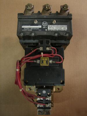
Every manufacturer is different (as others have noted). But here is an Allen Bradley 509.
For simplicity, I'm assuming we are using 480V for power and 120V for control, but many different options are available.
Power Flow
1) The 480V power flow starts with your 3-phase power conductors landing on L1, L2, and L3 at the top of the contactor. (Sometimes there will be a couple of smaller lugs connected to L1 and L2 so you can grab voltage for the high side of your control transformer.)
2) Power leaves through the lugs at the very bottom. In this picture they are partially hidden behind three other srcews (for the overload heaters). On the way from (1) to (2) current flows through (3) the contactor section, (4) the screws connecting the contactor with the overload block, and finally (5) the overload block. (If you look closely, you can see T1, T2, and T3 in white at the very bottom.)
3) This is where the power contacts are located. In a NEMA starter you can usually access these contacts, inspect them and replace them as needed. This can be tricky... until you figure out the trick. With some starters you have to remove screws, with others it's a push, twist, and pop kind of thing.
On this starter, there is an indicator that says OFF or ON. The two screws in the center of section (3) are where you connect to the coil of the starter. This particular starter has some sort of surge protector installed across the coil (the big blue thing).
4) These are the three screws that bolt the contactor section (above) to the overload block (below). A contactor + overloads = starter. (There are also three screws just above (4) - in a horizontal line - I'm not sure what these are.)
5) In section (5) you can see three black things with screws above and below them and a big white thing. The white thing is the reset button. You would push this in to reset the overload heaters after they trip on overload. The three black black things are the actual overload heaters. They can be replaced by removing the screws - two per heater. Once the heaters have been replaced you need to reset them by pressing the RESET button.
It also looks like there is a "tripped" indicator for the overload heaters (the word "tripped" is written vertically with an arrow pointing downward)... which is a mechanical arm behind a plastic window. When tripped, the arm pops up and the window does not appear black anymore.
Control Flow
A) If you have a starter with a control transformer, then the 480V feeding the transformer often comes from lugs connected to L1 and L2 at the starter. These conductors would connect to L1 and L2 at the transformer. You might have two fuses on the line side and one on the load side of the transformer (X1). You would typically bond X2 to ground. Which would make X1 the 120V conductor and X2 the neutral. In a very simple control circuit, X1 would go to through the Stop button and then connect to one side of the start button paralleled to the N.O. holding contacts on the starter.
B) These are the holding contacts. On this starter they are labeled "2" and "3", and the Stop button would be connected to "2", but often they are not labeled. Note that you can add more contacts. Either N.O. or N.C. or both. On this starter they mount on the left side (right below the existing set) and the right side just to the left of the my number (3). The other side of the Start button would connect to terminal "3". You can see that "3" has a red jumper connecting it to the coil of the starter. (It is partially hidden behind the blue surge suppressor.) This is the Hot side of the coil.
C) You can see another red jumper connected to the neutral side of the coil, but you can't see where it goes. On this starter, it wraps around behind the side of the overload block and connects to one side of a set of N.C. contacts.
D) These contacts are controlled by the overload heaters. They are actually located just below the starter near the T1 and T2 connections. From the overload contacts, a wire would typically connect back to X2 at the transformer, completing the circuit.
I know that was seems really complicated, but it is much easier once you get your hands on a real starter... I hope that was what you were asking for?