Transformer symbology

Status
Not open for further replies.
Not a calc question per se ... I have a client insisting on representing phasing for a 480-240/120 single phase transformer with a delta-wye combination shown on the one line diagram. I stated that this is for a three phase configuration and a symbol is not required since you have a phase-phase primary and phase-phase or phase-neutral secondary. Still, does anybody know of the use of symbol set for the 480-240/120 single phase transformer on a one line diagram?
 
There is no universal symbol, because there is no winding interconnection.

Following ANSI conventions your primary would simply be shown as 480V, and your secondary as 120/240V.

The format of 240/120 should be reserved for delta connected 3-phase 4-wire secondaries.
 
... Still, does anybody know of the use of symbol set for the 480-240/120 single phase transformer on a one line diagram?
Here's one I have seen...

xfmrone-line.gif
 
Not a calc question per se ... I have a client insisting on representing phasing for a 480-240/120 single phase transformer with a delta-wye combination shown on the one line diagram. I stated that this is for a three phase configuration and a symbol is not required since you have a phase-phase primary and phase-phase or phase-neutral secondary. Still, does anybody know of the use of symbol set for the 480-240/120 single phase transformer on a one line diagram?

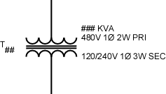
Never mind saw the 3-phase, didn't relize this single phase.
 
Last edited:
On schematic diagrams, a black dot is used on one side of the primary and the on the reference side of the primary.

But this wouldn't make any sense for a single line diargam. It really doesn' make any sense either unless you note the polarity of the reference voltages and the directions of the reference currents.
 
The dotting matters, because a 120/240 120kVA transformer can be used as 120v only 100kVA by paralleling up the output to get 120v 1000A or 240v 500A with optional center tap pull.

If you parallel up the secondary, you'll surely blow the primary fuse.
 
The dotting matters, because a 120/240 120kVA transformer can be used as 120v only 100kVA by paralleling up the output to get 120v 1000A or 240v 500A with optional center tap pull.

If you parallel up the secondary, you'll surely blow the primary fuse.
Dotting is not pertinent to one-line diagrams. I don't even see how you would do it when a 3? transformer is shown. The sysmbol is practically the same as the one I posted above.
 
Dots and Deltas and Ys -oh my

Dots and Deltas and Ys -oh my

Dotting is not pertinent to one-line diagrams. I don't even see how you would do it when a 3? transformer is shown. The sysmbol is practically the same as the one I posted above.

"Dotting" I think is the same as a Bar symbol used to denote polarity in current transfromers. It can be used on oneline drawings and three line metering and relay diagrams.
3 Phase transformer symbols should also include a "Y" and a "Delta" symbol ( Triangle. They should be drawn so the sides of the Y and the corresponding sides of the triangle are Paralle.
The european symbol for transformers is being used more now-two or three overlaping circles.
You guys are catching up.
You might eventually ditch HP in favor of kW.....
;)
 
Status
Not open for further replies.
Top