I think we all agree the answer to the wire bending is "no problem " (consider the bending radius of a conductor in a LB).
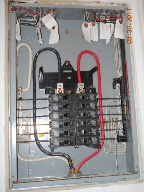
My old eyes (and "standard practice" on hundreds of panels) lead me to think the conductors on the left were equipment grounds. As mentioned by many, since this is not a service panel, your neutrals need to be isolated.
If the other cables are AC and the feed is AC, I see no other problems.
My old eyes (and "standard practice" on hundreds of panels) lead me to think the conductors on the left were equipment grounds. As mentioned by many, since this is not a service panel, your neutrals need to be isolated.
If the other cables are AC and the feed is AC, I see no other problems.