Ground Detection Question

Status
Not open for further replies.

tankfarms

Member
Hello,
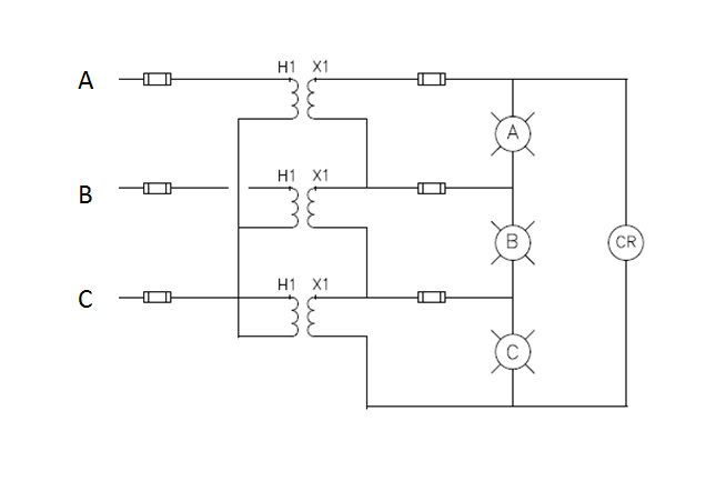
I have a ground detection system as shown below. It's on one of the 480V MCC's we have and it works through having 3 PT's with Wye-OpenDelta configuration. It basically works by detecting overvoltage between any two phases in which case a single phase ground would occur. My quesiton is: What's the proper way of setting the overvoltage relay "CR" as shown below. That is, what determines the overvoltage "pickup" settings? Are there any standards/industry guidelines out there specificying this? In this particular case, the PT's are 480V-120V, and the relay "CR" is a meter relay that has scale 0-300V. I noticed that most of the relays are set for overvoltage pickup somewhere around 150V, but not sure how this setting is dervied. Anyone can help explain this to me? Thanks.

MicrosoftPowerPoint-GndDetection2011711205729.jpg
 

rcwilson

Senior Member
Location
Redmond, WA
Sounds like you have a high resistance grounded 480/277 V system. The PT's are connected wye-broken delta, not wye- open delta.

Simplifying the math and forgetting about system charging currents: during an A phase to ground fault the voltages on VT's primaries will be: Vag=0v, Vbg= 480V, Vcg = 480V with Abg and Vcg 120 degrees apart. The VT secondaries will have 0v, 120V at 120 degrees and 120V at 240 degrees. The relay will see the sum of these voltages = 208V (phase to phase voltage for 120V, 120 degrees apart.)

If you set the relay too low you will get false trips or alarms during switching events. Too high and it won't pick up a high resistance fault. Rule of thumb is to set it at 50% of the nominal voltage for a solid fault, then adjust it as needed to minimize false alarms.

The meter relay probably has pointers to alarm above or below the setpoint. On some systems, the charging currents are unbalanced and create a voltage on the resistor during normal operation. The relay can be set and wired to alarm if that voltage goes away if the resistor or the VT's gets disconnected, burned up or turned off.
 

tankfarms

Member
Sounds like you have a high resistance grounded 480/277 V system. The PT's are connected wye-broken delta, not wye- open delta.

Simplifying the math and forgetting about system charging currents: during an A phase to ground fault the voltages on VT's primaries will be: Vag=0v, Vbg= 480V, Vcg = 480V with Abg and Vcg 120 degrees apart. The VT secondaries will have 0v, 120V at 120 degrees and 120V at 240 degrees. The relay will see the sum of these voltages = 208V (phase to phase voltage for 120V, 120 degrees apart.)

If you set the relay too low you will get false trips or alarms during switching events. Too high and it won't pick up a high resistance fault. Rule of thumb is to set it at 50% of the nominal voltage for a solid fault, then adjust it as needed to minimize false alarms.

The meter relay probably has pointers to alarm above or below the setpoint. On some systems, the charging currents are unbalanced and create a voltage on the resistor during normal operation. The relay can be set and wired to alarm if that voltage goes away if the resistor or the VT's gets disconnected, burned up or turned off.

Thanks! Very clear explanation. So if I take this "rule of thumb" of using 50% of the nominal voltage during a ground fault for the overvoltage pickup, it should really be 208*50% = 104 volt.

One of our overvoltage meter is set to pick up at 25V! And we've been getting some intermittent nuisance "ground fault alarms". This may well explain it. Not sure why it was set like that thou.
 

erickench

Senior Member
Location
Brooklyn, NY
The basic rule of thumb as given by Stallcup's is that the trip setting may be calculated from 10 to 50% of the OCPD as long as the 400 amp setting is not exceeded. Most designers start with 20% and increase the percentage as necessary.
 

rcwilson

Senior Member
Location
Redmond, WA
The basic rule of thumb as given by Stallcup's is that the trip setting may be calculated from 10 to 50% of the OCPD as long as the 400 amp setting is not exceeded. Most designers start with 20% and increase the percentage as necessary.

These are good settings for a solidly grounded system. If this is a high resistance grounded system, the fault current is probably limited to about 10 amps or less. Any ground fault overcurrent units will not pickup and trip, unless the first ground fault is not corrected in time and a second fault occurs on another phase.

The meter relay setting typically sounds an alarm so the maintenance electrician can correct the fault without shutting down the process. Some of the "nuisance" alarms could be true ground faults on a circuit like a sump pump that runs intermittently. When the pump is off, there's no ground fault and the problem is identified as a nuisance alarm.
 
Status
Not open for further replies.
Top