Correctly Connecting a Zig Zag Transformer for Line to Neutral Loads

Status
Not open for further replies.

smitty1701

Member
Location
boston, ma
Hello,

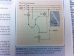
I have a question about properly connecting a Zig Zag transformer for line to neutral loads. I want to use a zig zag to derive a neutral line so that my system can be used with a 3-Phase Delta transformer, currently only supports Wye with a neutral. When i look in the NEC, specifically 450.7, it shows the neutral being taken from one of the legs of the zig zag. However when you look at 450.8 the neutral connection is where all the winding's of the zig zag meet. Do you really wire the zig zag differently if you want to use it for deriving a ground or use it for line to neutral loads? Thanks for any help
 

AdrianWint

Senior Member
Location
Midlands, UK
The wiring would be the same for both functions.

However, using a zig-zag to derive a neutral is not really 'the done thing'. Zig-Zag transformers usually have a low rating and should only really be used as a method to derive a ground reference on a delta system - hence they only carry current during a fault & not 24/7.

Using the zig zag to create a 'neutral' point on a delta system leads to zero sequence currents circulating in the delta winding, reducing its capacity & leading to additional heating.

Adrian
 

smitty1701

Member
Location
boston, ma
Hmm, i mean in the NEC is shows an example of using the zig zag to derive a neutral, so it must be an alright practice, see attached picture. And i do agree with you that its usually used to just derive a ground because most of the examples and information i have found on the web are applications for deriving a ground, not for line to neutral loads.

But it seems like you know of a better way to derive a neutral for line to neutral loads, how would you do it?

Thanks again for the help
 

Attachments

  • Photo Jul 28, 11 08 22 AM.jpg
    Photo Jul 28, 11 08 22 AM.jpg
    16.6 KB · Views: 11

AdrianWint

Senior Member
Location
Midlands, UK
Interesting, I have never seen a zig-zag transformer connected in that manner (as shown in your pic).

Far be it from me, a Brit, to question the NEC, but I think that drawing may be in error. Without a connection to the star point, I can't see what purpose the transformer serves and also, what about CT1, where is its secondary connection?

The circuit, as shown would simply ground one corner of the delta (which is an acceptable practice) but this wouldn't give a neutral... if fact, as shown, I think this setup would give 480V L1 - N, 480V L2-N & 0V L3-N.

However, everyday is a school day & I'm open to correction......'tis a very foolish engineer who claims to know everything.....

A better way to derive a neutral for a load of any size would be to use a delta/Wye transformer, grounding the star point.

Adrian
 

smitty1701

Member
Location
boston, ma
I completely agree with you, the diagram does not look correct and when i sat down with my fellow EE's they couldnt figure out how it would work either; thats why i figured i would see what someone thought on here. I also agree that we could be missing something here and maybe it does work somehow. I dont have great simulation software to simulate it either, we use TINA. The CT-1, CT-2 and CT-3 devices are just overload/differential fault/current sensing relays to indicate some type of internal fault. I wonder if there is a way to contact the NEC about this one and verify its correct, ill have to research that a little.

The Delta to Wye is something i considered but then i came across the zig zag and the NEC saying i could use it to derive a neutral, so it seemed more cost effective to me do that. This is also what we currently recommend our customer supplies if they are using a 3-Phase Delta, they must buy their own Delta/Wye transformer.

Thanks again
 

david luchini

Moderator
Staff member
Location
Connecticut
Occupation
Engineer
Hmm, i mean in the NEC is shows an example of using the zig zag to derive a neutral, so it must be an alright practice, see attached picture. And i do agree with you that its usually used to just derive a ground because most of the examples and information i have found on the web are applications for deriving a ground, not for line to neutral loads.

But it seems like you know of a better way to derive a neutral for line to neutral loads, how would you do it?

Thanks again for the help

Technically, It's not the NEC showing an example of a zig-zag to derive a neutral, its the commentary in the NEC Handbook.

The 1999 Handbook shows the same diagram, except that the neutral connection is at the center point as you would expect.
 

smitty1701

Member
Location
boston, ma
Well i think its an actual example of how to do it. Its says "Exhibit 450.7 illustrates the proper method of protecting a grounding autotransformer used to provide a neutral for a 3-phase system where necessary to supply a group of single-phase, line-to-neutral loads."

So it sounds like its showing you how to connect the line to neutral loads to the zigzag, otherwise what would the purpose of the illustration be?
 

cpinetree

Senior Member
Location
SW Florida
Same in 2008 Handbook

Same in 2008 Handbook

Technically, It's not the NEC showing an example of a zig-zag to derive a neutral, its the commentary in the NEC Handbook.

The 1999 Handbook shows the same diagram, except that the neutral connection is at the center point as you would expect.

The 2008 Handbook also shows the same diagram, except that the neutral connection is at the center point as you would expect.
 

cpinetree

Senior Member
Location
SW Florida
pic of 2008 handbook exhibit 450.7

pic of 2008 handbook exhibit 450.7

Hmm interesting, and it says that setup is used for Line to Neutral loads? Could you possibly post a picture?

If it needs to be bigger let me know.

Handbook_Ex450_7.JPG
 

rbalex

Moderator
Staff member
Location
Mission Viejo, CA
Occupation
Professional Electrical Engineer
The illustration shown in Post 3 simply cannot work no matter how sophisticated the relaying may be. To me, it appears to be a drafting error.

As others have mentioned, the illustration is not officially the NEC; it is from the NEC Handbook. (I'd like to know the year-and the editors) In the introductory material there will be a disclaimer saying something like:
Notice Concerning Liability: Publication of this handbook is for the purpose of circulating information and opinion among those concerned for fire and electrical safety and related subjects. While every effort has been made to achieve a work of high quality, neither the NFPA? nor the contributors to this handbook guarantee the accuracy or completeness of or assume any liability in connection with the information and opinions contained in this handbook.

All that said, depending on the size of the installation, the level of relaying necessary, even if the basic connections were correct, would probably have me seeking another means of deriving a neutral.
 

smitty1701

Member
Location
boston, ma
Well thank you so much for all the help on this issue! I figured there had to of been a drafting mistake because it made no sense to my colleague and I.

Also the handbook i got that picture from was the 2011 Handbook, Editor-in-Chief is Mark W. Earley; and managing editor Jeffrey S. Sargent.
 

smitty1701

Member
Location
boston, ma
Also this is the response i got from the NEC after i sent an email about the mistake.


Brandon,
I checked with the engineering department, and this is the reply that I got:

Looks like he is entirely correct. Not sure how or why the drawing was changed. It was correct in the last two editions of the handbook. We will look into it.

If there is anything further I can do to assist you please do not hesitate to contact me.
 

rbalex

Moderator
Staff member
Location
Mission Viejo, CA
Occupation
Professional Electrical Engineer
Both Mark Earley and Jeff Sargent are outstanding men. They have both been the NFPA's Chief Electrical Engineer at one time or another. As I said, It appears to be a drafing error - they get missed ocassionally.
 

glene77is

Senior Member
Location
Memphis, TN
Both Mark Earley and Jeff Sargent are outstanding men. They have both been the NFPA's Chief Electrical Engineer at one time or another. As I said, It appears to be a drafing error - they get missed ocassionally.

And your "drafing' error is excused for the same reason :)
 
Status
Not open for further replies.
Top