Rick Christopherson
Senior Member
I've brought this topic up a few times in the past, but I just wanted to reiterate how an unbonded transformer can result in a floating system, whose secondary voltages are limited only by the voltage of the primary. This was made painfully obvious tonight after an emergency troubleshooting call tonight.
Going back to the beginning, 5 to 7 years ago, I got called out to the church my father belongs to, to diagnose why stage performers were complaining of getting shocked while on stage. The simple Edison tester would light up all three lights, which didn't make much sense. A quick check of voltages on the stage outlets showed 80 volts neutral-to-ground. Aside from that, everything was checking out fine. I had 120/240 at the lugs, and I had continuous ground with the rest of the building.
After a little digging, I learned that the stage was fed with a small isolation transformer to supply clean 120/240 from a 3-phase system. That's when everything clicked, and I realized it was an unbonded separately derived system. I spoke with the State Inspector the next day and he remembered the original inspection in 2000, but both he and the EC didn't realize it constituted a separately derived system. So I chalked it up to a simple oversight and didn't give it much more thought.
Tonight I got called back out to the same church to troubleshoot a voltage anomaly in another part of the church (the main office space) that's completely separate from the stage. In this case, some maintenance was being done up in the ceiling. The circuit was de-energized, but when the conductor bundle was pulled out of a piece of equipment, sparks flew. This was a little disturbing because the circuit was confirmed dead. While I was on the phone, I had them check the voltages in the load center located in the office space. Everything checked out, except ground-to-neutral was 120 volts, and ground-to-Phase-B was 240 volts.
Forgetting what was discovered 7 years ago, I originally assumed a floating ground. I remembered the unbonded transformer from 7 years ago, but I knew this was a completely separate system supplying the offices, so another unbonded transformer was not high on my list of suspicions. This was also the main part of the original building, and spanned 75% of the original building. It took a while to determine that the office load center was being supplied from a 150A disconnect that was labeled "kitchen", which was fed from a 37kVA 480:240/120 transformer.
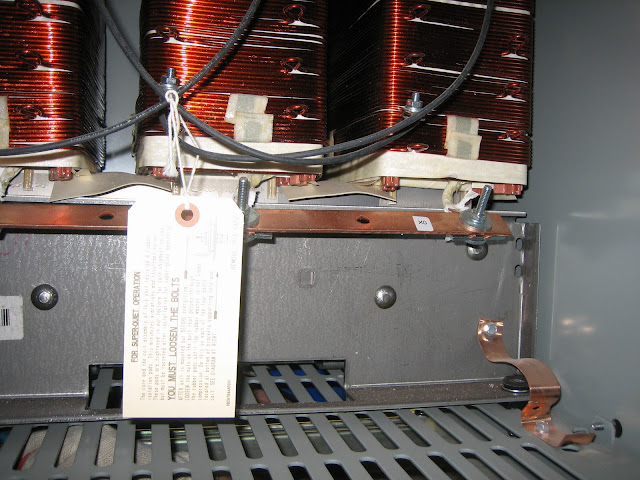
After getting permission to cut power to that whole wing, I opened the disconnect below the transformer, and once again, discovered an unbonded transformer. Except this is a main transformer that feeds most of the original building outside of the 480/277 and 208/120 loads.
This condition has existed for 12 years, and it is amazing that no one has been hurt. It's also amazing that no one had discovered it before now either. Finding this on the small stage transformer seemed like a simple oversight. Finding this on the main transformer feeding most of the building is a little more disconcerting. It has me wondering whether any of the transformers in the building are bonded, and due to expansions over the years, there are quite a few of them. They were all installed by the same EC. I'm expecting a call from the EC in the morning, and I am going to request that they inspect all of the transformers in all of the additions that have been made over the years.
In light of finding this on a main transformer, I am wondering if the EC didn't mistakenly assume that all transformers are internally bonded. Is this a common assumption with commercial EC's?
Going back to the beginning, 5 to 7 years ago, I got called out to the church my father belongs to, to diagnose why stage performers were complaining of getting shocked while on stage. The simple Edison tester would light up all three lights, which didn't make much sense. A quick check of voltages on the stage outlets showed 80 volts neutral-to-ground. Aside from that, everything was checking out fine. I had 120/240 at the lugs, and I had continuous ground with the rest of the building.
After a little digging, I learned that the stage was fed with a small isolation transformer to supply clean 120/240 from a 3-phase system. That's when everything clicked, and I realized it was an unbonded separately derived system. I spoke with the State Inspector the next day and he remembered the original inspection in 2000, but both he and the EC didn't realize it constituted a separately derived system. So I chalked it up to a simple oversight and didn't give it much more thought.
Tonight I got called back out to the same church to troubleshoot a voltage anomaly in another part of the church (the main office space) that's completely separate from the stage. In this case, some maintenance was being done up in the ceiling. The circuit was de-energized, but when the conductor bundle was pulled out of a piece of equipment, sparks flew. This was a little disturbing because the circuit was confirmed dead. While I was on the phone, I had them check the voltages in the load center located in the office space. Everything checked out, except ground-to-neutral was 120 volts, and ground-to-Phase-B was 240 volts.
Forgetting what was discovered 7 years ago, I originally assumed a floating ground. I remembered the unbonded transformer from 7 years ago, but I knew this was a completely separate system supplying the offices, so another unbonded transformer was not high on my list of suspicions. This was also the main part of the original building, and spanned 75% of the original building. It took a while to determine that the office load center was being supplied from a 150A disconnect that was labeled "kitchen", which was fed from a 37kVA 480:240/120 transformer.
After getting permission to cut power to that whole wing, I opened the disconnect below the transformer, and once again, discovered an unbonded transformer. Except this is a main transformer that feeds most of the original building outside of the 480/277 and 208/120 loads.
This condition has existed for 12 years, and it is amazing that no one has been hurt. It's also amazing that no one had discovered it before now either. Finding this on the small stage transformer seemed like a simple oversight. Finding this on the main transformer feeding most of the building is a little more disconcerting. It has me wondering whether any of the transformers in the building are bonded, and due to expansions over the years, there are quite a few of them. They were all installed by the same EC. I'm expecting a call from the EC in the morning, and I am going to request that they inspect all of the transformers in all of the additions that have been made over the years.
In light of finding this on a main transformer, I am wondering if the EC didn't mistakenly assume that all transformers are internally bonded. Is this a common assumption with commercial EC's?