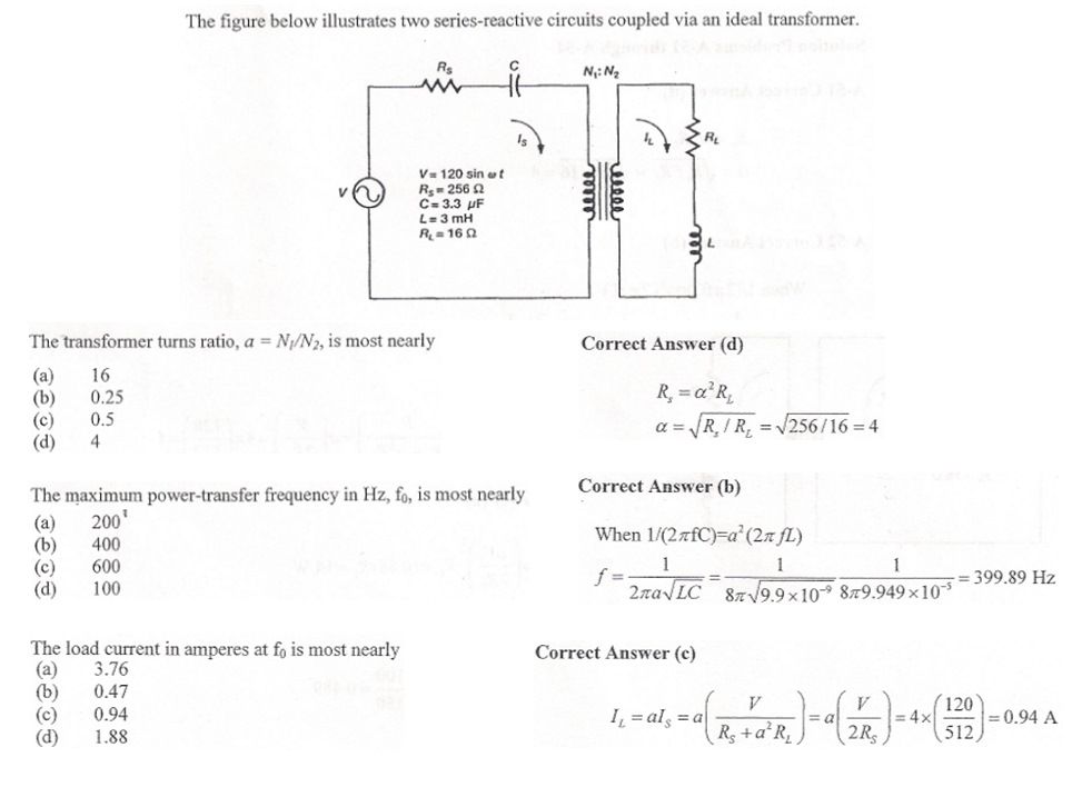
I'm studying for my PE exam and encountered a sample question like below. I don't quite understand the third solution provided. How come we are not using impedance (Z) for calculation but instead we only use resistance (R). Also, to calculate the load current, I thought it would be just to divide the secondary voltage (1240/4 = 30V) by the impedance of the secondary circuit, but using such thinking got me the wrong answer.
Can anyone help explain the third question and its provided solution?
Can anyone help explain the third question and its provided solution?
")