- Location
- Windsor, CO NEC: 2023
- Occupation
- Hospital Master Electrician
Exactly where did you check the phase rotation?
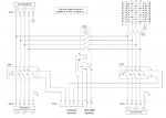
Phase rotation was checked at the output of the internal UPS transformer with one meter, and a second meter was applied to the bypass feeder input at the UPS. Essentially, the two sources of power (inputs) at the UPS were checked for rotation and matched.
I did not see where the neutrals between the two systems were common? If they are not (USP's often having floating output neutral, or where is it bonded?) then I vote with your statement above.
Both transformers have a system bonding jumper, the neutral of each is connected to the Equipment Grounding Conductors. Thus, all neutrals involved are connected together.
The maintenance bypass panel switches neutrals enough to keep neutrals segregated at the panel itself. With all three switches there open, there is no continuity between the neutral bus and the equipment grounding conductor bus.
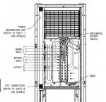
I erred. The proper model (or closer to it) is here.APC does build some hokey equipment. I would be careful, it will not be *their* fault. The UPS document in the link above shows a unit that is 208 volt Y input with the bypass internal and your one line drawing shows a unit that is 480 volt (delta?) input.
There's an internal static bypass, and an internal mechanical bypass, and a maintenance bypass panel with bypasses in it... Which one are you referring to?You are saying the bypass is external?
")
Which?The bypass document link above does not open.
No. The only error I have seen on occasion is "UPS in Bypass Due to Fault," but it seems to go away on it's own.Do you get a "System Not Synchronized to Bypass." error?
So, I don't need to worry about this phase shift? The UPS output would always be tied to the bypass input cycle?Agreed, the inverter (UPS) output is typically sync'ed to the (static) bypass since it has to be able to switch over in <1 cycle.
I know I did include that in the measurements I took in the field, but I did not include them. I hadn't thought of checking which "phase group" the output was tied to until just now. When we reenergize the UPSes I will do just that to confirm Zbang and Ron's train of thought.120915-2347 EDT
My reading of the original post was that the voltage measurements were made between the output of the internal transformer, before the rectifiers, and with the bypass feeder.
I did not read into the original statement that the UPS output was being compared with the bypass supply, but possibly that is what was implied.
Often the UPS manufactures use transformers with a phase shift, your bypass transformer needs to match theirs and often is sold as part of the UPS sale.
What is the benefit of a phase shifting transformer?
The salesman mentioned that the transformer inside the UPS is an isolation transformer, which at one point led me to believe that this was the source of our voltage oddities. However, when I think of the term "isolation transformer" I immediately associate an ungrounded neutral conductor to achieve the isolation. Since there is a system bonding jumper that I can see and measure physically (it is roughly a 4 AWG conductor visible in the bottom of the UPS) then this transformer's isolating properties have been defeated by this system bonding jumper, have they not?
I guess the overriding question is, under normal conditions is the load supplied by the batteries or by the source charging the batteries? If the source supplying the batteries is not supplying the load, then there would be no occasion for the two systems to come into direct contact, right? Therefore no concern on my end is warranted...right?
I will also measure voltages at the maintenance bypass panel and see if the phase shift shows there when I get a chance.
I appreciate all the help guys, this is a first for me and it has a 30-year master electrician, the tech, myself and the sales guy confused.