Gate controlling lights

Status
Not open for further replies.

uwireme

Member
Location
Cottonwood, CA
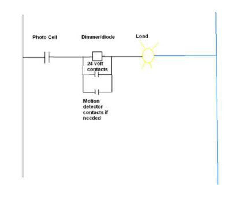
I would like to turn on some lights from a gate controller that would also include a photo cell and a dimmer switch, will my attached drawing work or will I have problems with the dimmer and or photo cell.

The dimmer does not have a line and load but the photo cell does.

Customer would like dusk to dawn operation (most of the time) and ability to dim lights. He is concerned if the dimmer switch is off when he arrives at the gate at night he would like the ability to open the gate and the lights would turn on. There is a 24Vdc timed relay in the controller for this.
 

Attachments

  • gate lighting.pdf
    94.8 KB · Views: 0

dicklaxt

Senior Member
The gate controller could work in different ways and you are saying he wants the lights to function on/off via the gate actuation and a timed off DC relay thats easily done.The client wants the ability to dim the lights and thats easily done.

The thing I don't understand is what the photo cell is for, can you explain this operation in more detail,also whats the dimming feature for?

I don't see your schematic doing anything but turning the lights on and off,,the dimmer and photo cell are not doing anything unless the OP explanation is wrong.

dick
 
Last edited:

hillbilly1

Senior Member
Location
North Georgia mountains
Occupation
Owner/electrical contractor
The way it is drawn, it appears that the only thing the gate contact does is bypass the photo cell AND the dimmer, the light will come on anytime day or night when the gate is opened. You need to parrallel the gate contact with the dimmer only, that way if the photocell is active, the light will be on dim, then when the gate is activated the light will go to full brightness, and will not be burning during the day when the gate is opened.
 

dicklaxt

Senior Member
The way it is drawn, it appears that the only thing the gate contact does is bypass the photo cell AND the dimmer, the light will come on anytime day or night when the gate is opened. You need to parrallel the gate contact with the dimmer only, that way if the photocell is active, the light will be on dim, then when the gate is activated the light will go to full brightness, and will not be burning during the day when the gate is opened.

right on ,thats why we need a better explanation of who's on first when what's on second and why's on third,,,,sorry the devil made me do it.

dick
 

Hv&Lv

Senior Member
Location
-
Occupation
Engineer/Technician
The way I see this as drawn, the lights are on at night when the gate is not doing anything. When the gate opens, the lights will come on full brightness whether it is day or night. At night, the lights will be bright when the gate motor is energized, and will stay bright until the timed contactor times out. Once the gate is done with it's operation, the timer on your contactor opens at your set time, and the lights will go to the dim setting.
 

dicklaxt

Senior Member
The way I see this as drawn, the lights are on at night when the gate is not doing anything. When the gate opens, the lights will come on full brightness whether it is day or night. At night, the lights will be bright when the gate motor is energized, and will stay bright until the timed contactor times out. Once the gate is done with it's operation, the timer on your contactor opens at your set time, and the lights will go to the dim setting.


Good thought HvLv and if thats the sequence of operation then we should change the schematic to a off/on variable resistor for the NO "D" contact and add a 120 VAC powered sensor w/NO contact for the NO "PC" contact.

dick
 

hurk27

Senior Member
here is a simple sequence of operation that might work for you if using only incandescent lights only:

Hot to a common photo cell wired as normal, the red wire to a dimmer or just a diode rated for the load, then from the dimmer/diode to the hot of the fixtures with the neutral of both the fixtures and photo cell returning to the supply neutral.

place the 24 volt contacts parallel across the dimmer/diode.

Sequence of operation:

When dusk falls and photo cell closes its contact, current will flow through the dimmer/diode to the load and it will come on in a dim mode, if gate opener is activated 24 volt contacts close and bypasses the dimmer/diode and lights become full bright.

A motion sensor can be also added across the 24 volt contacts to brighten the lights when motion is detected, use a sensor with a dry output contacts for easiest of wiring

Gatelightcontroler-1.jpg
 
Last edited:

uwireme

Member
Location
Cottonwood, CA
The way I see this as drawn, the lights are on at night when the gate is not doing anything. When the gate opens, the lights will come on full brightness whether it is day or night. At night, the lights will be bright when the gate motor is energized, and will stay bright until the timed contactor times out. Once the gate is done with it's operation, the timer on your contactor opens at your set time, and the lights will go to the dim setting.


This is correct...but now thinking to add another photo cell before the contactor so the light will not turn on in the day time. I am working with only so many wires.

I am concerned about the dimmer, will it be ok working like this and same for the photo cell that is before the dimmer. If the dimmer is at 50% from line to load then the gate opens and sends 100% from load to line then to the photo cell will all be well??


here is a simple sequence of operation that might work for you if using only incandescent lights only:

Hot to a common photo cell wired as normal, the red wire to a dimmer or just a diode rated for the load, then from the dimmer/diode to the hot of the fixtures with the neutral of both the fixtures and photo cell returning to the supply neutral.

place the 24 volt contacts parallel across the dimmer/diode.

Sequence of operation:

When dusk falls and photo cell closes its contact, current will flow through the dimmer/diode to the load and it will come on in a dim mode, if gate opener is activated 24 volt contacts close and bypasses the dimmer/diode and lights become full bright.

A motion sensor can be also added across the 24 volt contacts to brighten the lights when motion is detected, use a sensor with a dry output contacts for easiest of wiring

Gatelightcontroler-1.jpg


This would be the way to go, but wire is in and cant be changed
 

Hv&Lv

Senior Member
Location
-
Occupation
Engineer/Technician
This is correct...but now thinking to add another photo cell before the contactor so the light will not turn on in the day time. I am working with only so many wires.
24VDC photocontrol?

I am concerned about the dimmer, will it be ok working like this and same for the photo cell that is before the dimmer. If the dimmer is at 50% from line to load then the gate opens and sends 100% from load to line then to the photo cell will all be well??
I'm not sure how the TRIAC in the dimmer will handle being backfed. I would guess they won't be affected , and the photocontrol should be ok IMO. Personally, I would try it.
You have piqued my interest now...
 

hurk27

Senior Member
I guess I'm confused as to what you have???

First you can not put the photo cell after a dimmer as it will affect its operation because of the thermo switch contacts in them, if you place any switch or contacts ahead of a photo cell the photo cell will not operate until the contacts close and if they close during the day time then the lights will come on for a couple minutes.

Now with that being said, I'm totally confused as to why you cant put the above component's in my diagram at the same location as the 24 volt relay?

the dimmer does not even need a neutral in most cases and can be placed in-line at any point in the circuit as long as it is after the photocell, the photo cell will need a neutral but seems like it can also be placed at the location of the 24 volt relay, or if the lights are on a separate circuit then the gate, it can be placed at the source of power.

There is no reason to have two photocells in-line with the load, just by-pass any after the first photocell, this will eliminate any troubleshooting problems down the road.

If the above components can be placed at the location of the 24 volt relay then I cant see any problem with adding the above component's to this location and connecting with existing wiring if there is a hot, load, and neutral at that location?
 

hurk27

Senior Member
Ok I been looking at you diagram.PDF and I think I see the problem, and a few others if I'm right?

from your diagram and statements, you have a 24 volt contactor at the gate control box.

You have a dimmer at the house fed by a photo cell.

Then you have hot feed from the gate control box to the lights fed through the 24 volt contactor with it picking up power at the gate control box?

If the above is true then you have a couple problems?

First is both the gate circuit and the light circuit the same circuit or are they different circuits?
If they are different circuits then you can not do what you are trying if you don't move the photo cell and dimmer out to the gate control box so it can be fed from the same circuit.

Second if these two circuits are from different legs in the panel you will back feed 240 volts across the dimmer and photo cell and when the gate opener is activated Kaboom!!!

third even if they are on the same legs in the panel, the 24 volt contactor will be tyeing two circuits together through the photocell and dimmer and this will allow more current before the breakers will trip causing wiring to be overloaded beyond there rating, still a no no.

I'm just guessing from your diagram and the statement that the wires are already run and can't be changed, which told me you have an existing wall switch fed by a existing or added added photocell feeding some yard lights, and wanted to add a way to turn them on via the gate controller, this meant there was an existing feed for the lights from this switch and a existing feed to the gate controller, you ran a wire feed to the controller from the lights so you could use the 24 volt relay to turn on the lights?

If the above is true then all you need is a wireless sending unit and receiver from www.smarthome.com, put the sending unit at the gate controller and the receiver with dry contacts across the dimmer, might require cutting in a single gain box to install it next to dimmer.
 
Last edited:

uwireme

Member
Location
Cottonwood, CA
Ok I been looking at you diagram.PDF and I think I see the problem, and a few others if I'm right?

from your diagram and statements, you have a 24 volt contactor at the gate control box.

You have a dimmer at the house fed by a photo cell.

Then you have hot feed from the gate control box to the lights fed through the 24 volt contactor with it picking up power at the gate control box?

If the above is true then you have a couple problems?

First is both the gate circuit and the light circuit the same circuit or are they different circuits?
If they are different circuits then you can not do what you are trying if you don't move the photo cell and dimmer out to the gate control box so it can be fed from the same circuit.

Second if these two circuits are from different legs in the panel you will back feed 240 volts across the dimmer and photo cell and when the gate opener is activated Kaboom!!!

third even if they are on the same legs in the panel, the 24 volt contactor will be tyeing two circuits together through the photocell and dimmer and this will allow more current before the breakers will trip causing wiring to be overloaded beyond there rating, still a no no.

I'm just guessing from your diagram and the statement that the wires are already run and can't be changed, which told me you have an existing wall switch fed by a existing or added added photocell feeding some yard lights, and wanted to add a way to turn them on via the gate controller, this meant there was an existing feed for the lights from this switch and a existing feed to the gate controller, you ran a wire feed to the controller from the lights so you could use the 24 volt relay to turn on the lights?

If the above is true then all you need is a wireless sending unit and receiver from www.smarthome.com, put the sending unit at the gate controller and the receiver with dry contacts across the dimmer, might require cutting in a single gain box to install it next to dimmer.


Thanks for the input...by your drawing it looks like I would need another wire from the dimmer box, but wiring cant change.
gl2.jpg
 
Status
Not open for further replies.
Top