kingpb
Senior Member
- Location
- SE USA as far as you can go
- Occupation
- Engineer, Registered
It appears to me that 695.3(A) requires the transformer to be able to carry the locked rotor current of the fire pump. I think it must be able to supply the normal loads in addition to the fire pump LRC.
That section only applies "Where the service or system voltage is different from the utilization voltage of the fire pump motor". That would not apply to the utility transformer.I think this is a little "gray". 695.5 makes it clear that a transformer does not have to be rated to carry the LRC, just the overcurrent device. The "gray" for me is, does this apply to a utility transformer?
That does bring up a question, if this second transformer is not sized to carry the LRC, what good does it do to have the utility transformer sized to carry that current?
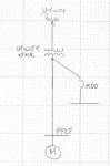
Based on the one-line, does the utility transformer have to carry the LRC of fire pump and 100% of the service load, or just 125% of the fire pump plus 100% of the service load?
, after all the NEC cannot dictate to utilities.
Exactly. Around here, the utility can size their transformers any way they want. The NEC doesn't apply.