voltage drop calculations

Status
Not open for further replies.

JJsparks

Member
Location
N Michigan
I posted a question a couple of months ago reguarding voltage drop for a run of light poles that I am installing. Many replies very helpful and got me going in the right direction. I would like to confirm my thinking on wire sizing since once its done theres no turning back.

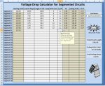
A typlical run has about 10 incandescent poles, each pole drawing 150 watts each. The closest pole from the soure is 400 feet, each additional pole is approximately 80 feet down line from the next. My thinking is I calculate the first pole at the total load of the entire run( 10 x 150 watts = 1500). I come up witha number 6 use copper for the correct sizing. My next step is to calculate the next pole using the longer wire length but with the load reduced by one fixture or 1.23 amps. I would continue to use this method until I am at the last post where I will have a sigificant wire length but only a load requirements of 1.25 amps. Is my thinking and calculations correct or am I off base. Thank you for any help you may provide.
 

Dennis Alwon

Moderator
Staff member
Location
Chapel Hill, NC
Occupation
Retired Electrical Contractor
You need to be careful in calculations. Online calculators generally allow a 3% drop. If each calculation has a 3% drop then the voltage down the line will be accumulated. If you start with a 0% VD then onward I believe this would be a better approach. So I would like to see a total of 3% at the last outlet (light) not at the first light.
 

Smart $

Esteemed Member
Location
Ohio
You use total load to first load. Then distance between first load to second load using total load minus first load. Then distance between second load an third load using total load minus first and second loads. And so on to last load.

You first need to determine what your total voltage drop limit will be to the last load (typically 3%). The Vd % to the first load cannot be less than this, and the Vd % between loads will have to be an incremental portion of the percentage diffence between first and last loads.

If you want to run just one size of wire you can determine by calculating the distance to load center...

Distance from source to first load times fist load current = F1
Distance from source to second load times second load current = F2
....
Distance from source to last load times last load current = Fn

(F1 + F2 + ... + Fn) ? total current = Distance to load center
Use the distance to load center to determine size of wire and voltage drop as if a single load at that distance.

If you want to use two or more sizes of wire, the preceding will provide a basis for sizing the wires.
 
Last edited:

JoeStillman

Senior Member
Location
West Chester, PA
Another way to do it is to multiply the amps in each circuit segment by the length of each circuit segment. Then you add up the total ampere-feet. If you multiply this by the ohms-per-foot for a given wire size, you have the voltage drop to the farthest point.

Or, you can divide the allowable voltage drop (in volts) by the ampere-feet and get ohms-per-foot. Use this number to look up the required wire size in an impedance table such as NEC table 9.

When you are adding up the ampere-feet, you ignore side branches. Just calculate the total for the longest branch.
 

Smart $

Esteemed Member
Location
Ohio
Another way to do it is to multiply the amps in each circuit segment by the length of each circuit segment. Then you add up the total ampere-feet. If you multiply this by the ohms-per-foot for a given wire size, you have the voltage drop to the farthest point.

Or, you can divide the allowable voltage drop (in volts) by the ampere-feet and get ohms-per-foot. Use this number to look up the required wire size in an impedance table such as NEC table 9.

...
These are variations (or shortcuts, if you prefer) of the distance to load center method I posted earlier.
 

G._S._Ohm

Senior Member
Location
DC area
You've got your lengths and your loads so all you need is the impedance of each wire length.

I've used a spreadsheet to work backwards from the last light on the string working at 120v - 3% and worked upstream. It's very tedious but there is less chance of error using a spreadsheet.
The power to an incand. lamp varies as V^1.6. It will probably be close enough if you assume constant resistance loads.

I'll run this out if I get a chance; that's the best way to find out if I end up chasing my tail.
10 poles, 150w, 400' then 80'. 120v?
 
Last edited:

G._S._Ohm

Senior Member
Location
DC area
Well, this gets interesting.

I assumed the wire feeding all the lamps at 80' was 0.1 ohm (the RWs below) and the 400' (RW1) was 0.4 ohm, and the wire resistance being << the lamp resistance, and lamp #10 had 116.4v and all lamps measured 96 ohms.
As you can see, we ran out of voltage between lamps 3 and 2.
Q: how do you want to distribute the wire resistances to minimize cost while having the source voltage at 120v instead of at 126.8?

0.1 =RW10
0.1 =RW9
0.1 =RW8
0.1 =RW7
0.1 =RW6
0.1 =RW5
0.1 =RW4
0.1 =RW3
0.1 =RW2
0.4 =RW1


116.4 =VL10
96 =RL10
1.2125 =IL10=VL10/RL10
116.52125 =VS10=VL10+IL10*RW10

116.52125 VS10 = VL9
96 =RL9
2.426263021 =IL9=IL10+VL9/RL9
116.7638763 =VS9=VL9+IL9*RW9


116.7638763 VS9 = VL8
96 =RL8
3.642553399 =IL8=VL8/RL8
117.1281316 =VS8=VL8+IL8*RW8


117.1281316 VS8 = VL7
96 =RL7
4.862638104 =IL7=VL7/RL7
117.6143955 =VS7=VL7+IL7*RW7


117.6143955 VS7 = VL6
96 =RLx
6.087788056 =ILx=VLx/RLx
118.2231743 =VS6=VLx+ILx*RWx


118.2231743 VS6 = VL5
96 =RLx
7.319279455 =ILx=VLx/RLx
118.9551022 =VS5=VLx+ILx*RWx


118.9551022 VS5 = VL4
96 =RLx
8.558395103 =ILx=VLx/RLx
119.8109417 =VS4=VLx+ILx*RWx


119.8109417 VS4 = VL3
96 =RLx
9.806425746 =ILx=VLx/RLx
120.7915843 =VS3=VLx+ILx*RWx


120.7915843 VS3 = VL2
96 =RLx
11.06467142 =ILx=VLx/RLx
121.8980514 =VS2=VLx+ILx*RWx


121.8980514 VS2 = VL1
96 =RLx
12.33444278 =ILx=VLx/RLx
126.8318285 =VS1=VLx+ILx*RWx
 
Last edited:

Smart $

Esteemed Member
Location
Ohio
Well, this gets interesting.

...
The ampere-feet value computes to 9500.

120 ? 3% = 3.6V

3.6V ? 9500A-ft = 0.00038ohms/ft or 0.38ohms/kft...

Looking at #4 copper (0.31ohms/kft) to run as one size to 3% limit.
 
Last edited:

G._S._Ohm

Senior Member
Location
DC area
The ampere-feet value computes to 9500.

120 ? 3% = 3.6V

3.6V ? 9500A-ft = 0.00038ohms/ft or 0.38ohms/kft...

Looking at #4 copper (0.31ohms/kft) to run as one size to 3% limit.
I get 119.9v with 380 milliohms/ft.

There is some minimum cost distribution of wire sizes for this application but at the moment trial and error is the only way I know to find it. In general the last lamp gets smaller wire.

If you post $/ft for various wire sizes I might hit on it. IIRC, this is a linear algebra/operations research problem.
 
Last edited:

Smart $

Esteemed Member
Location
Ohio
I get 119.9v with 380 milliohms/ft.

There is some minimum cost distribution of wire sizes for this application but at the moment trial and error is the only way I know to find it. In general the last lamp gets smaller wire.

If you post $/ft for various wire sizes I might hit on it. IIRC, this is a linear algebra/operations research problem.
With the one-size calculation resulting in 0.38ohms/kft, and #4 at 0.31 and #6 at 0.49, he could probably transition at some point and still maintain 3% limit. Actually, if he wanted less variation in lamp brightness, he could run #6 wire from the source and transition to #4 towards the end. Or perhaps even tolerate slightly dimmer lights run #6 all the way.
 

G._S._Ohm

Senior Member
Location
DC area
With these wire sizes I get

0.0392 =RW10
0.0392 =RW9
0.0392 =RW8
0.0392 =RW7
0.0392 =RW6
0.0392 =RW5
0.0392 =RW4
0.0392 =RW3
0.0392 =RW2
0.124 =RW1
gives


120.0589117 =VS1

With smaller wire and some OCPDs (depending on their $/amp) there might be even a smaller cost implementation.

If you guys didn't ask, I'd never learn anything! :)
 
Last edited:

Smart $

Esteemed Member
Location
Ohio
At 120 V with 1120' (400'+80'x9 poles) total distance might cost a larger $ on cable. Have you considered stepping up to a higher voltage? Is this direct burial cable?
Another alternative might be to run 5 and 5 on mwbc. Vd is close to same as running at 240V, but have to use 3 wires.


Which reminds me that my earlier calculation is off. I only used one way distance, and unfortunately current doesn't just run one way. :slaphead:


So using one-way voltage drop limit...

1.8V ? 9500A-ft = 0.00019ohm/ft or 0.19ohm/kft.

So would be looking at #2 copper.

So running mwbc will probably need #4 to #6.
 

G._S._Ohm

Senior Member
Location
DC area
What wire sizes???
The CU or AL wire sizes that correspond to the listed resistance values for 160' and 800' conductor loop distances.

It seems that three wire sizes might do better as far as the minimum wire cost; one for the 400', one for the first five lamps and one for the last five.
 

G._S._Ohm

Senior Member
Location
DC area
It's becoming clear to me that the spreadsheet needs more columns, e.g., wire resistance for the distance for AL, same for CU, $/ft for that gauge AL (which depends on the length purchased), same for CU, and a sum posted at the bottom of these last two columns.

The optimum for voltage drops is almost certainly not the same as the optimum for cost, since physics does not take supply & demand into account.
This larger spreadsheet will, though.
 
Status
Not open for further replies.
Top