
jmellc
Senior Member
- Location
- Durham, NC
- Occupation
- Facility Maintenance Tech. Licensed Electrician
Sorry, been busy.
I only got readings on 2 leads, I forget which. Got 2.1 ohms. All other readings blank. I took motor to a shop. Capacitor was shot, needed a new bearing & an internal lead was broken from back of terminal board. I had no way to remove terminal board without disassembling motor. Board is larger than wiring box opening.
I will put motor back in Wed.
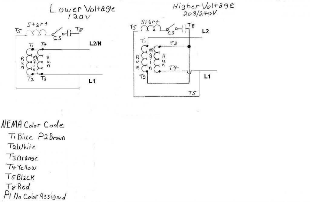
I am now looking at the motor. For sure, we only have 4 terminals. No jumper bars as on hurk 27's photo. BTW hurk, thanks for the chart. I will print that on some index cards & have them handy for future cases.
Low is: T1....Line 1 T2....Red, Orange T3....Open T4....Blk, Wht, Line 2
High is: T1....Line 1 T2....Open T3....Wht, Red, Orange T4....Blk, Line 2
Rotation CCW, Swap red & black to reverse
Thanks again for all the help. Does anyone know a good book on motors? I have never worked that much with them. I have connected a lot & changed leads for voltage. I studied them a little in apprenticeship class but never worked with anyone servicing them. I need a bit more knowledge to "carry around".
I only got readings on 2 leads, I forget which. Got 2.1 ohms. All other readings blank. I took motor to a shop. Capacitor was shot, needed a new bearing & an internal lead was broken from back of terminal board. I had no way to remove terminal board without disassembling motor. Board is larger than wiring box opening.
I will put motor back in Wed.
I am now looking at the motor. For sure, we only have 4 terminals. No jumper bars as on hurk 27's photo. BTW hurk, thanks for the chart. I will print that on some index cards & have them handy for future cases.
Low is: T1....Line 1 T2....Red, Orange T3....Open T4....Blk, Wht, Line 2
High is: T1....Line 1 T2....Open T3....Wht, Red, Orange T4....Blk, Line 2
Rotation CCW, Swap red & black to reverse
Thanks again for all the help. Does anyone know a good book on motors? I have never worked that much with them. I have connected a lot & changed leads for voltage. I studied them a little in apprenticeship class but never worked with anyone servicing them. I need a bit more knowledge to "carry around".
")