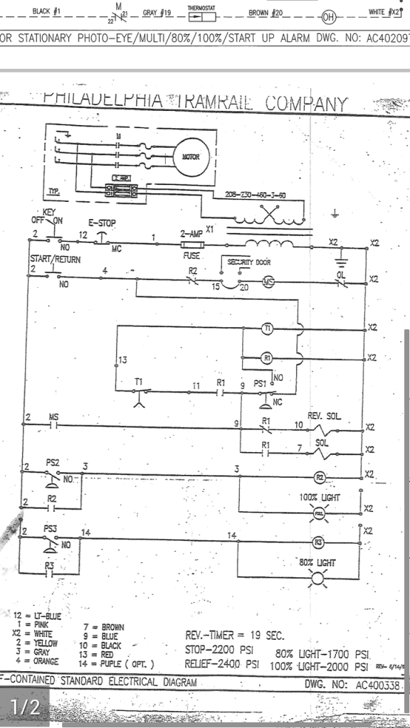
 This is a hydraulically operated compactor. The machine is hooked to a 40 yard compactor. When I push start now it runs forward then back and shuts off. I want to be able to push the start button and have it cycle three times. I have tried timers but the speed of the ram is always different depending on the material it is compacting. I have attached a copy of the schematic any help is greatly appreciated. If you can help can you also show me how to alter the schematic to make it work.
You are using an out of date browser. It may not display this or other websites correctly.
You should upgrade or use an alternative browser.
You should upgrade or use an alternative browser.
Changing a motor control circuit to repeat three times.
- Thread starter ryandumas
- Start date
- Status
- Not open for further replies.
Strathead
Senior Member
- Location
- Ocala, Florida, USA
- Occupation
- Electrician/Estimator/Project Manager/Superintendent
Just get on the phone and call Allen Bradley Technical support. I am reasonably sure you can do this with a PLC, but there are probably devices that will do it mechanically also.View attachment 7907This is a hydraulically operated compactor. The machine is hooked to a 40 yard compactor. When I push start now it runs forward then back and shuts off. I want to be able to push the start button and have it cycle three times. I have tried timers but the speed of the ram is always different depending on the material it is compacting. I have attached a copy of the schematic any help is greatly appreciated. If you can help can you also show me how to alter the schematic to make it work.
Agree. PLC wouldn't need to be anything more than a so-called micro-controller. Perhaps all that is needed is a counting relay.... I am reasonably sure you can do this with a PLC, but there are probably devices that will do it mechanically also.
[Strathead, your schematic is too small to discern pertinent details.]
Phil Corso
Senior Member
- Location
- Boca Raton, Fl, USA
Ryan...
You do realize the modification to multiple-cycles will upset some Waste-Management types!
Regards, Phil Corso
You do realize the modification to multiple-cycles will upset some Waste-Management types!
Regards, Phil Corso
Ooops...!!! Just realized that comment should have been directed to Ryan.....
[Strathead, your schematic is too small to discern pertinent details.]
Cow
Senior Member
- Location
- Eastern Oregon
- Occupation
- Electrician
I'd probably use a smart relay, most manufacturers have one. Or a Click PLC from Automation Direct. Both are super easy to program.
Generally speaking, smart relay is just another term for a micro-controller or micro-PLCI'd probably use a smart relay, most manufacturers have one. Or a Click PLC from Automation Direct. Both are super easy to program.
ptonsparky
Tom
- Occupation
- EC - retired
The CLICK is an easy and cheap way to go. To bad i cant read the diagram at all...at least not on this droid screen.
I can't get the pic to load bigger but here is a link to another forum I posted on. Hope I'm not breaking any posting rules. http://www.electriciantalk.com/f28/making-industrial-compactor-repeat-48523/#post900464
kwired
Electron manager
- Location
- NE Nebraska
- Occupation
- EC
Agree. PLC wouldn't need to be anything more than a so-called micro-controller. Perhaps all that is needed is a counting relay.
[Strathead, your schematic is too small to discern pertinent details.]
The "counting relay" is likely the easiest thing to incorporate into whatever controls are already there, they are not that easy to read.
I can't get the pic to load bigger but here is a link to another forum I posted on. Hope I'm not breaking any posting rules. http://www.electriciantalk.com/f28/making-industrial-compactor-repeat-48523/#post900464
The "counting relay" is likely the easiest thing to incorporate into whatever controls are already there, they are not that easy to read.
Been a while since I've dealt with count control, but what I gather from looking at a few such products is that most use a DC-triggered count input. That would require additional interfacing for an AC control circuit.Check with Eaton. They have count control which used to be sold (it may still be) under the "Durant" name.
What you are asking to do should be easily done with this product at a reasonable price.
Does anyone know of a simple counting relay that uses an on-off AC 60Hz input?
Short of that, I'm now leaning more towards a "smart relay" as the better option. A "smart relay" could replace T1, and depending on its I/O configuration, possibly R1, R2, and/or R3.
Ryan (assuming that is your name),
If you want assistance with this through completion, more details are in order.
What is the control voltage? I don't see it noted anywhere on the schematic.
Make and model of T1, R1, R2, and R3. Mostly need to know contact configuration, poles and form... but other details may become relevant later.
Also schematic implies pressure switch trip points, but would like confirmation if these are factory set and the info is on a nameplate... make and model wouldn't hurt either.
ptonsparky
Tom
- Occupation
- EC - retired
Control voltage is 120 from what I can see. Not that it should matter if it were something other.
We are missing details though.
We are missing details though.
Been a while since I've dealt with count control, but what I gather from looking at a few such products is that most use a DC-triggered count input. That would require additional interfacing for an AC control circuit.
Does anyone know of a simple counting relay that uses an on-off AC 60Hz input?
Short of that, I'm now leaning more towards a "smart relay" as the better option. A "smart relay" could replace T1, and depending on its I/O configuration, possibly R1, R2, and/or R3.
It has been 13 years since I was an application enginer for countrol also. I don't recall that a DC trigger is required. It may be that a simple dry type contact closure would be required. Give Eaton a call as you have an extremely simple application.
It should be a simple count to three and then reset.
I would have to get familiar with the schematic in order to find where I can get a cycle complete ontact closure to initiate the count countrol to close the contact in the start circuit to recycle the compactor at the end of the first cycle repeating the cycle two more times before allowing it to stop.
That is a likely possibility that I considered... includes what I meant about interfacing and also why I asked for more detailed info on existing relays. I sometimes forget to be simple and blunt about what I am thinking... I don't recall that a DC trigger is required. It may be that a simple dry type contact closure would be required....

I would have to get familiar with the schematic in order to find where I can get a cycle complete ontact closure to initiate the count countrol to close the contact in the start circuit to recycle the compactor at the end of the first cycle repeating the cycle two more times before allowing it to stop.
Same here. Looks like R1 energized-deenergized controls forward and reverse solenoids, respectively... but there are no travel limit switches involved... only pressure switches... so would need to know their location on hydraulics. Currently assuming PS2 and PS3 on ram-forward line and PS1 on ram-return line.
I was thinking that during the first cycle the control ckt would close a dry contact to the count control which the count control would count one and reinitiate the starter by closing a contact in the start circuit for the second time which would then close a dry contact to the countrol which would reinitiate a third start after which the count control would not initiate any more starts.
If you had an extra inlk available on th MS which closes when MS is de-energized that would work for a dry contact closure.
Thus all of your connections would be located between the start/return PB and the MS. It should be fairly simple.
Then a N/O contact of a control relay would be connected across the start PB. The count control would close the control relay, closing the N/O contact to initiate a start. The contact closure only needs to be momentary and not maintained which you may have to give some though to.
I do see that you have an Estop which would be a maintained open contact that would not allow the count control to continue to cycle the compactor if the Estop were to be pushed. But some thought must also be given to what sequence that you would be in if you released the E-stop to assure that it wouldn't automatically restart the compactor sequence. I would understand that you would want to manually push the start bottom to begin the cycle.
I trust that this makes sense to you becaause sometimes a control sequence can seem to make perfect sense but yet again it may be as clear as mud.
ptonsparky
Tom
- Occupation
- EC - retired
A PLC is the best way to go here. Replacing the whole control, or having it run in parrallel with the existing system is your choice.
Information gleaned from a visit to the other forum suggest you have a fair idea as to what needs to be done, and your liabilities.
Information gleaned from a visit to the other forum suggest you have a fair idea as to what needs to be done, and your liabilities.
JoeStillman
Senior Member
- Location
- West Chester, PA
- Occupation
- Electrical PE
Here's the existing sequence as I see it;
Press START/RETURN. MS starts, R1 allows FWD solenoid to energize and all seals in through PS1. When PS1 hits setpoint, MS drops out. Pressing and holding START/RETURN at this point energizes R1 and begins the countdown of T1. MS runs with REV solenoid energized until release of START/RETURN or T1 times out. It depends on the operation of PS1 though. I'm not sure what is supposed to make the motor stop if PS1 lets MS seal in after pressing RETURN.
Modify the controls with a set of FWD/REV relays as shown. operation is as above, except 1F prevents MS from dropping out on operation of PS1. Instead, the solenoids reverse until T1 times out, then go forawd again until the third cycle. On the third reverse cycle, 3R unlatches 1F etc. and takes over sealing MS until R1 final T1 cycle, then KR lets it all drop off.
It all depends on the make/break setpoints of PS1. This diagram is probably worth what you've paid for it.
.jpg")
Press START/RETURN. MS starts, R1 allows FWD solenoid to energize and all seals in through PS1. When PS1 hits setpoint, MS drops out. Pressing and holding START/RETURN at this point energizes R1 and begins the countdown of T1. MS runs with REV solenoid energized until release of START/RETURN or T1 times out. It depends on the operation of PS1 though. I'm not sure what is supposed to make the motor stop if PS1 lets MS seal in after pressing RETURN.
Modify the controls with a set of FWD/REV relays as shown. operation is as above, except 1F prevents MS from dropping out on operation of PS1. Instead, the solenoids reverse until T1 times out, then go forawd again until the third cycle. On the third reverse cycle, 3R unlatches 1F etc. and takes over sealing MS until R1 final T1 cycle, then KR lets it all drop off.
It all depends on the make/break setpoints of PS1. This diagram is probably worth what you've paid for it.
- Status
- Not open for further replies.