In existing control, the following components will drop out MS under normal operation: PS1 change of state, PS2 change of state energizes R2 and R2 NC contacts open, security door is opened, or OL trips.... I'm not sure what is supposed to make the motor stop if PS1 lets MS seal in after pressing RETURN.
...
You are using an out of date browser. It may not display this or other websites correctly.
You should upgrade or use an alternative browser.
You should upgrade or use an alternative browser.
Changing a motor control circuit to repeat three times.
- Thread starter ryandumas
- Start date
- Status
- Not open for further replies.
:lol:... This diagram is probably worth what you've paid for it.
...
Anyway, FWIW, I considered using staged, latching relays similar to what you have diagrammed... but considering the cost compared to a counting or smart relay...????
JoeStillman
Senior Member
- Location
- West Chester, PA
- Occupation
- Electrical PE
Ice cube relays are inexpensive, but you'll spend a lot on sockets, a box, labor to wire it up, labor to wire it up again without mistakes, etc.
It looks like the controls are not autimatically reversing at present. I wonder why it was designed that way to begin with? I'd talk to the manufacturer about why it doesn't reverse on its own.
It looks like the controls are not autimatically reversing at present. I wonder why it was designed that way to begin with? I'd talk to the manufacturer about why it doesn't reverse on its own.
hillbilly1
Senior Member
- Location
- North Georgia mountains
- Occupation
- Owner/electrical contractor
The easiest way I see of doing this, is to wire the start button to control an off delay timer, which in turn, it's contact would replace the start button in the control circuit. Set the delay short of what the average time of three cycles, wire a second relay with its coil parralleled with the reverse solenoid, the N/C contact from that relay would be wired in series with the start contact from the T2. This will cause the ram to continue to cycle until it opens due to the pressure switch that controls the reversal solenoid.
JoeStillman
Senior Member
- Location
- West Chester, PA
- Occupation
- Electrical PE
The easiest way I see of doing this, is to wire the start button to control an off delay timer, which in turn, it's contact would replace the start button in the control circuit. Set the delay short of what the average time of three cycles, wire a second relay with its coil parralleled with the reverse solenoid, the N/C contact from that relay would be wired in series with the start contact from the T2. This will cause the ram to continue to cycle until it opens due to the pressure switch that controls the reversal solenoid.
That would work nicely, if you could get the timing right. I think you have a 19 second margin for error.
I'm not sure what your relay paralleled with the REV solenoid does though. Wouldn't it stop the process on the first REV cycle?
How about this one?
.jpg")
Attachments
hillbilly1
Senior Member
- Location
- North Georgia mountains
- Occupation
- Owner/electrical contractor
That would work nicely, if you could get the timing right. I think you have a 19 second margin for error.
I'm not sure what your relay paralleled with the REV solenoid does though. Wouldn't it stop the process on the first REV cycle?
How about this one?
View attachment 7921
The relay may not be needed, but I threw it in there to reset the start signal in case there was a conflict when PS1 opened when the ram was reversed. When the timer dropped out the reverse solenoid and the added relay, it would close the start signal again until the off delay timer timed out.
That would simulate someone holding in on the START/RETURN button for the amount of delay set on T2....
How about this one?
...
According to a post by OP'er in "other" forum's thread, holding in on the START/RETURN button causes the ram upon Reverse to immediately change back to Forward. That would be fine if the intended operation was to recompress several times... but I believe the desired operation is to fully retract the ram and "grab" another pass worth of trash.
hillbilly1
Senior Member
- Location
- North Georgia mountains
- Occupation
- Owner/electrical contractor
That would simulate someone holding in on the START/RETURN button for the amount of delay set on T2.
According to a post by OP'er in "other" forum's thread, holding in on the START/RETURN button causes the ram upon Reverse to immediately change back to Forward. That would be fine if the intended operation was to recompress several times... but I believe the desired operation is to fully retract the ram and "grab" another pass worth of trash.
That's why I put in the relay controlled by the reverse solenoid, because I figured that might happen if the start input is maintained, that would allow the reverse solenoid to finish its cycle before starting over. I'm assuming that once PS1 reaches its operating pressure, it triggers the reverse solenoid, with R1 as a holding contact until T1 times out, PS1 probably opens as soon as the ram is reversed, if the start signal is still closed, it would re-energize the forward solenoid. (There are no other forums than Mike Holt! :lol
") (Also an HOA switch would have to be installed to allow the ram to come back when compactor is full)
(Also an HOA switch would have to be installed to allow the ram to come back when compactor is full)
Last edited:
But MS coil has to be energized while R1 coil is not, for the ram to return (REV solenoid energized). That cannot happen if PS1's pressure is above its set point.That's why I put in the relay controlled by the reverse solenoid, because I figured that might happen if the start input is maintained, that would allow the reverse solenoid to finish its cycle before starting over. I'm assuming that once PS1 reaches its operating pressure, it triggers the reverse solenoid, with R1 as a holding contact until T1 times out, PS1 probably opens as soon as the ram is reversed, if the start signal is still closed, it would re-energize the forward solenoid. (There are no other forums than Mike Holt! :lol
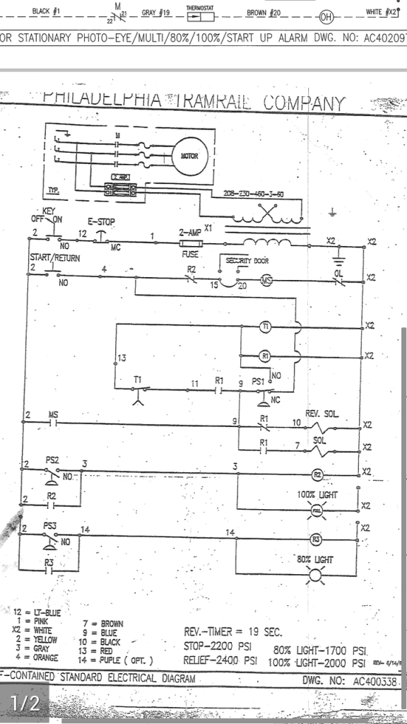
It would help to know where in the hydraulic system PS1 is located and its trip pressure. The schematic implies PS2 and PS3 trip at 2000 and 1700 PSI respectively. Does PS1 trip at 2200 PSI? Is it before or after solenoid valve? If after, in Fwd or Rev lines?
ptonsparky
Tom
- Occupation
- EC - retired
I used PicoSoft 6 for this but it should work with PicoSoft 3 which is free.
I01 is an input from the load side of the Start button
I02 is an input from the line side of the start button.
Q1 contacts energize an additional control relay that has NC contacts in series with the CR2 coil but not the 100% indicating light. This allows the 100% light to come on at each cycle.
I03 is on the load side of the 100% pressure switch
Pressing the Start button begins the sequence but is then disabled for two more cycles
The 100% switch advances the counter each time it closes. After 3 cycles the counter and latched output are reset allowing R2 to open the circuit in normal fashion.
Pressing the Stop or Locking out the key switch will Stop the sequence and also reset the Counter and Latched relay.
View attachment 7923
All standard disclaimers apply as well as any others that I or any other person can possibly think of. It is also worth what you have paid.
Last edited:
hillbilly1
Senior Member
- Location
- North Georgia mountains
- Occupation
- Owner/electrical contractor
But MS coil has to be energized while R1 coil is not, for the ram to return (REV solenoid energized). That cannot happen if PS1's pressure is above its set point.
It would help to know where in the hydraulic system PS1 is located and its trip pressure. The schematic implies PS2 and PS3 trip at 2000 and 1700 PSI respectively. Does PS1 trip at 2200 PSI? Is it before or after solenoid valve? If after, in Fwd or Rev lines?
I kept looking at the diagram, and something just didn't look right, I finally figured out my logic was backwards, PS1 is tripped as soon as the ram starts forward, that starts T1, once it times out, R1 drops out, while the ram returns, PS1 drops out, when the ram reaches full return, PS1 activates again, opening the control circuit, turning off the pump because there's no start signal.
I started with that theory but look at the diagram closer. If PS1 is tripped as soon as ram starts forward (and START/RETURN is no longer depressed) what maintains an energized MS???I kept looking at the diagram, and something just didn't look right, I finally figured out my logic was backwards, PS1 is tripped as soon as the ram starts forward, ....
The more I think about it, I have to wonder if the diagram is even accurate...???
Last edited:
ptonsparky
Tom
- Occupation
- EC - retired
I started with that theory but look at the diagram closer. If PS1 is tripped as soon as ram starts forward (and START/RETURN is no longer depressed) what maintains an energized MS???
The more I think about it, I have to wonder if the diagram is even accurate...???
I drew and ran this on Constructor. The only way I could get things to work was to manually sequence the N/O & N/C contacts of PS1, as if they had a slight overlap in the timing. Not what I would expect. The page notation of 1/2 in the lower left doesn't help either.
My PicoSoft drawing makes some assumptions on the operation of PS1.
Scratch that, I was mistaken, that doesn't work either.
Last edited:
Here's what I'm seeing. Depiction shows PS1 tripped. Assuming MS is the starter coil for the (hydraulic pump) motor. As soon as PS1 trips, motor stops.I drew and ran this on Constructor. The only way I could get things to work was to manually sequence the N/O & N/C contacts of PS1, as if they had a slight overlap in the timing. Not what I would expect. The page notation of 1/2 in the lower left doesn't help either.
My PicoSoft drawing makes some assumptions on the operation of PS1.
Scratch that, I was mistaken, that doesn't work either.
Part of what has me wondering is why the "start" switch is labeled START/RETURN (hereafter S/R). The only way I see this working, PS1 is an overpressure switch, i.e. greater than 100% at 2000 PSI, and between pump and solenoid valve. For discussion, we have to set initial conditions: the last cycle completed without going to 100% mode, ram is completely retracted, and 0% pressure on hydraulic system.
S/R button is pressed. Because R1 is not immediately energized, the REV solenoid is energized through R1 NC. The ram travels backwards to end of travel, then PS1 trips on overpressure. This energizes R1 and T1, which then become latched through R1 NO"1" and T1 "NC". R1 NO"2" energizes FWD solenoid, and on forward ram travel, PS1 resets. This all has to occur while S/R button is depressed. If S/R button is released prior to PS1 resetting, motor stops and process must be repeated (or, if last cycle did not end with ram retracted, ram retracts until PS1 trips then system stops [provided S/R is not held depresed]... ready for new cycle).
I'll stop here to await confirmation on my thinking being correct (or corrected
).
Last edited:
hillbilly1
Senior Member
- Location
- North Georgia mountains
- Occupation
- Owner/electrical contractor
I've been going to run it through a Trilogic program I have on a mini tower I have, but it takes a good 20 minutes for it to start up because of the antivirus software, I don't even mess with it. Love the iPad!
ptonsparky
Tom
- Occupation
- EC - retired
Here's what I'm seeing. Depiction shows PS1 tripped. Assuming MS is the starter coil for the (hydraulic pump) motor. As soon as PS1 trips, motor stops.
Part of what has me wondering is why the "start" switch is labeled START/RETURN (hereafter S/R). The only way I see this working, PS1 is an overpressure switch, i.e. greater than 100% at 2000 PSI, and between pump and solenoid valve. For discussion, we have to set initial conditions: the last cycle completed without going to 100% mode, ram is completely retracted, and 0% pressure on hydraulic system.
S/R button is pressed. Because R1 is not immediately energized, the REV solenoid is energized through R1 NC. The ram travels backwards to end of travel, then PS1 trips on overpressure. This energizes R1 and T1, which then become latched through R1 NO"1" and T1 "NC". R1 NO"2" energizes FWD solenoid, and on forward ram travel, PS1 resets. This all has to occur while S/R button is depressed. If S/R button is released prior to PS1 resetting, motor stops and process must be repeated (or, if last cycle did not end with ram retracted, ram retracts until PS1 trips then system stops [provided S/R is not held depresed]... ready for new cycle).
I'll stop here to await confirmation on my thinking being correct (or corrected
Ok, I think.
I can assign reactions to the pressure switches. I based them on the Hyd Motor operation under normal conditions. Under the conditions you gave PS1 is in a pressurized state. 17 seconds is on the timer. 10 seconds is assigned to PS2 and 8 seconds to PS3. 100% and 80% respectively. PS1 is assigned 2 seconds. Press & hold start button for 2 seconds, PS1 changes state because FWD Sol is energized and pressure has dropped in the Reverse side. S/R can be released. MS Circuit holds in, @ 8 sec 80% comes on, @10 sec 100% comes on, CR2 energizes and drops out holding circuit of MS. CR2 & CR3 are held until Stop is pressed & reset.
hillbilly1
Senior Member
- Location
- North Georgia mountains
- Occupation
- Owner/electrical contractor
I started with that theory but look at the diagram closer. If PS1 is tripped as soon as ram starts forward (and START/RETURN is no longer depressed) what maintains an energized MS???
The more I think about it, I have to wonder if the diagram is even accurate...???
I wonder that also, R1 and T1 has to be energized for the forward motion of the ram to work, then once T1 times out, it would drop out R1, causing the ram to reverse, but I'm like you, how are they keeping the hydraulic pump running?
Ok, I think.
I can assign reactions to the pressure switches. I based them on the Hyd Motor operation under normal conditions. Under the conditions you gave PS1 is in a pressurized state. 17 seconds is on the timer. 10 seconds is assigned to PS2 and 8 seconds to PS3. 100% and 80% respectively. PS1 is assigned 2 seconds. Press & hold start button for 2 seconds, PS1 changes state because FWD Sol is energized and pressure has dropped in the Reverse side. S/R can be released. MS Circuit holds in, @ 8 sec 80% comes on, @10 sec 100% comes on, CR2 energizes and drops out holding circuit of MS. CR2 & CR3 are held until Stop is pressed & reset.
The 80% relay and light just indicates the bale is almost full, while the 100% locks the ram out at the extended position when the bale is full, this would happen only after several compaction strokes, so I don't think that is it. The timer times only the forward motion of the ram. Something is missing we are not seeing.:?
I wonder that also, R1 and T1 has to be energized for the forward motion of the ram to work, then once T1 times out, it would drop out R1, causing the ram to reverse, but I'm like you, how are they keeping the hydraulic pump running?
The 80% relay and light just indicates the bale is almost full, while the 100% locks the ram out at the extended position when the bale is full, this would happen only after several compaction strokes, so I don't think that is it. The timer times only the forward motion of the ram. Something is missing we are not seeing.:?
That would be a "100% compressed" cycle. The ram will stay in the extended position, until e-stop is pressed or key is turned off to reset R2 (as there is no normal "STOP"). S/R would then have to be pressed (and released) again for ram to return to retracted position. When ram is fully retracted, PS1 trips and motor stops (MS drops out). T1 and R1 may become latched, but if MS has dropped out, T1 will just time out with no ram action... unless S/R is pressed again during this period. Then immediate FWD travel would occur... but how far forward the ram would get before T1 times out (or PS2 trips) would depend on when S/R was pressed in the T1 timing period.Ok, I think.
I can assign reactions to the pressure switches. I based them on the Hyd Motor operation under normal conditions. Under the conditions you gave PS1 is in a pressurized state. 17 seconds is on the timer. 10 seconds is assigned to PS2 and 8 seconds to PS3. 100% and 80% respectively. PS1 is assigned 2 seconds. Press & hold start button for 2 seconds, PS1 changes state because FWD Sol is energized and pressure has dropped in the Reverse side. S/R can be released. MS Circuit holds in, @ 8 sec 80% comes on, @10 sec 100% comes on, CR2 energizes and drops out holding circuit of MS. CR2 & CR3 are held until Stop is pressed & reset.
****
A "not 100% compressed" cycle will not trip PS2 and energize R2. Assume T1 times out and PS2 has not tripped, nor does it at any time in the cycle (PS3 action is irrelevant to cycling). The control should complete a full FWD and REV cycle.
What I am uncertain of is whether T1 is supposed to time out before ram gets to end of FWD travel... because if it doesn't, PS1 would become pressurized and trip again at the end of ram FWD travel, and motor stops (MS drops out) with ram extended. If T1 times out before end of FWD travel, REV should be triggered and a full cycle should occur.
Seems like the logic is off just a bit.... :happyyes: ...but I guess it works.
Last edited:
hillbilly1
Senior Member
- Location
- North Georgia mountains
- Occupation
- Owner/electrical contractor
I figured it out, PS1 is a over pressure switch on the reverse stroke, when the start button is pressed, MS closes, but it is still in reverse mode, while the start button is keeping MS engaged, PS1 changes state, flipping it to forward mode, PS1 drops back out, maintaining MS even though the start button is no longer pressed, once T1 times out, the reverse solenoid is energized, but because it is not under load, PS1 does not change states until the ram is fully retracted. Once it is retracted, the pressure jumps up changing the state of PS1, dropping out MS because the start button is not closed.
ptonsparky
Tom
- Occupation
- EC - retired
Ignoring PS2 & 3 makes it easier.
Pressing the S/R either reverses it to full retraction and high PS1 or sends it forward which is time controlled only. MS is held, in once PS1 looses pressure, via R1 NO contacts and T1 NC contacts. After the delay of 17 seconds both TR1 & R1 drop out, energizing the Rev, which stays on until PS1 changes state. MS then drops out. S/R starts the cycle over.
or yes, what the danged fast fingered hillbilly 1 said
Last edited:
- Status
- Not open for further replies.