jumper
Senior Member
- Location
- 3 Hr 2 Min from Winged Horses
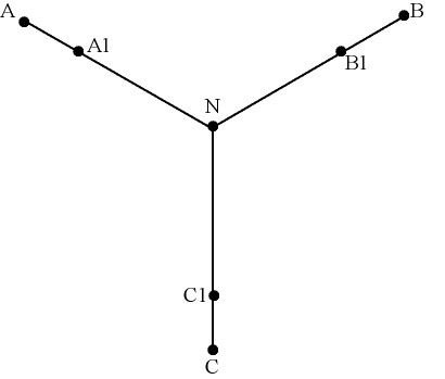
is there a way to upload a quick drawing as I may not be making myself clear about this install
You can use a site such as photobucket, or the upload link for attachments icon-looks like a paper clip, or PM me and I will send email address and post it for you.