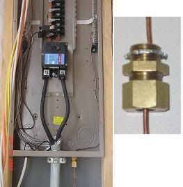
Does anyone else think that using a green screw as your main bonding jumper is weak.

Status
Not open for further replies.

Flux

Member
Location
Atlanta GA
In a service rated 200 amp QO disco the only current path for the overcurrent or lighting strike to travel leaving the 2/0 aluminum SER EG would be a green 8 gauge screw through the neutral bus into the main OCPD disco metal enclosure I have the EG lug bolted to. Is it just me or is that weak compared to the 2/0? I am thinking about putting in a double barrel 2/0 lug in place of the the single provided and use a piece of the #4 grounding electrode wire as the main bonding jumper to the extra lug provided on the neutral bar that is not sized for the 2/0 EG but will fit a #4. Whats ya think?
 

copper chopper

Senior Member
Location
wisconsin
I hear ya, we just put 8 new square D panels 225 amp in and each of them had this one- 1/4-20 screw, allen head holding the neuteral lug in place. we had to re-tap 2 of them to 3/8 because it stripped out when installing the fedders. kinda cheesy even for square D.:eek:hmy:
 

Flux

Member
Location
Atlanta GA
Both are compliant NEC says it may be a green screw or a wire sized in accordance with 250.66 but that calls for a
#4 piece of copper attached with mechanical lugs and like Chopper said otherwise you are relying on a threaded in
my case 2 treads in the metal enclosure to provide a path for all the ground fault current. Its my first project as my
own company and a family members house so I am going a little over board with it Square D QO two ground rods plus
cold water. I am attaching all that to essentially two steel treads and a number 8 screw it just seems like such a weak
way to tie all the other grounding components of a system together after the work put in for the other components
so you go from 2/0 AL to to 2 steel treads :? though it is code compliant as we all know the NEC is a minimum not a
good design manual.
Hey Chopper what brand do you like?
 

hurk27

Senior Member
I think we are over thinking this and mixing up what current that will flow through this screw.

First most of these screws are about a #10, and about a couple of inch's long, the impedance of such a short screw is very low, also the only current that should ever flow through that screw is a ground fault, because the code requires that the grounding electrode conductors are to be landed on the neutral bar unless the grounding bar is connected to the neutral by a wire or bus bar.

Majority of a lightning strike will flow on other paths in a building so very little will ever flow across that screw, most will follow the water pipe and gas piping in a building and believe it or not many times it Will follow cable and phone lines.

As for fault current it is such a fast duration that it will never come close to enough heat to damage the connection because the current is much higher in a ground fault that the breaker open very fast, this is one of the reasons why when sizing grounding conductors from table 250.122 the size is much smaller then the current carrying conductors.

As for over loads, you should not have any normal current on the grounding as your current should be hot to hot, or hot to neutral.

In a proper installation that little screw will fault thousands of amps without any damage as long as the breaker opens like it should and the screw has been tightened to the requirements of the manufacture.

Ever open a re-linkable fuse and see how small the aluminum element is on a hundred amp fuse.

Also the fact that fault current really has nothing to do with the size of the main breaker, as it is possible to have a higher fault current on a 100 amp service that is close to the transformer then a 200 that is away from a transformer, much of the amount of fault current will depend upon the impedance of the path to the source, this is where understanding more about electrical theory is so important, on a dwelling service where there in no coordination of the breakers you could have a fault on a 30 amp circuit that will open both the 30 amp breaker and the 200 amp main, because both can have the same instantaneous fault current time curves that will present the same level of fault to both and if it exceeds both trip curves it will open both, this is an example of that current will always be equal in a series circuit.
 

infinity

Moderator
Staff member
Location
New Jersey
Occupation
Journeyman Electrician
If you don't trust the screws you can always use these for added protection on all of your GEC's.

KennyClamp.jpg
 

Flux

Member
Location
Atlanta GA
I guess I see your point and I have been through both AC and DC theory and I thought about the voltage drop in relation to the size of the equipment ground vs the screw but it is still odd to me.
Nice Infinity I will have to keep an eye out for that.
 

kwired

Electron manager
Location
NE Nebraska
I guess I see your point and I have been through both AC and DC theory and I thought about the voltage drop in relation to the size of the equipment ground vs the screw but it is still odd to me.
Nice Infinity I will have to keep an eye out for that.

Both size and length of a conductor factor into voltage drop calculations.

Lets also look at the primary intended current path, even as you have been trying to describe it. Say we have a surge on the 2/0 incoming conductor, it next hits the neutral bus, from the neutral bus hopefully the lowest impedance to ground we will find is a grounding electrode conductor attached to the neutral bus. The function of the green screw bonding jumper is not to tie to a grounding electrode, it is to connect the equipment grounding system to the service grounded conductor.
 
Location
NE (9.06 miles @5.9 Degrees from Winged Horses)
Occupation
EC - retired
Anyone see one of these fail?

Fail? Loaded question. Hard to tell if it was torqued adequately in the first place, or not at all. We have seen instances where the connection failed, but they were preceeded by an open neutral to the transformer, PP bonding of building steel, and lack of GEC to the neutral bar, etc, etc. You get the picture. To many other failures to install correctly that led to the failure, if you want to call it that.
 

jim dungar

Moderator
Staff member
Location
Wisconsin
Occupation
PE (Retired) - Power Systems
It it not just that the screw is NEC compliant.
It has also actually been tested, and witnessed by UL, to carry its rated fault current.

As others have pointed out, this is a bonding item not a GEC.
 

GoldDigger

Moderator
Staff member
Location
Placerville, CA, USA
Occupation
Retired PV System Designer
It it not just that the screw is NEC compliant.
It has also actually been tested, and witnessed by UL, to carry its rated fault current.

As others have pointed out, this is a bonding item not a GEC.

And any external fault current, such as lighting induced, will hopefully enter the box on a grounding conductor rather than the grounded conductor, making the capacity of the bonding means moot.
 

jes25

Senior Member
Location
Midwest
Anyone see one of these fail?

An apprentice I was working with got a fish tape in a 200A panel and caused a pretty big fault that instantly opened the 200A main. I noticed that green screw had a bunch of arc marks around it where it contacted the neutral bar. Could have been loose I suppose.
 

Flux

Member
Location
Atlanta GA
I used a #4 solid to go from a double barrel lug that the Equipment Ground is terminated on that is bolted to the enclosure in the Service Disco to the neutral bus that the electrode wire is bonded on, just to be sure and it helps me sleep at night:D.
 
Status
Not open for further replies.
Top