D!NNy
Senior Member
- Location
- San Luis Obispo
Transformer Configuration:
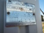
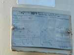
In the attached picture shows the primary voltage of the transformer is "12000 Delta X 20780 Delta".
Questions:
1. I believe all the time voltage provided by SCE or PG&E is phase to Phase unless they mention it as line to ground voltage? am i correct.
2. how would we determine the primary voltage without contacting the PG&E? Does this one has something to do with lead connections?
3. PG&E confirmed that this transformer is fed by a 21kV system? then lead connections should be shown as 3-4?
4. can some one clarify how this lead connections, voltage and transformer configurations connections shown in the picture are related to each other?
5. Can this transformer be used for both 12kv and 21kv primary voltage for different connections?
Thanks in Advance