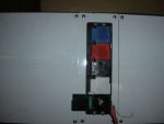
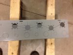
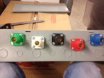
Here a set of slots connect the five conductor entries. You can see the steel plate that is on the underside of the enclosure which is needed due to the various prepunched KOs and weakening of the enclosure from the slots.
View attachment 9086
Quick, dirty and cheap to match a tight budget.
Just a small point, and one that can be ignored in the interests of simplicity in directing fabrication:
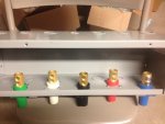
The EGC, the green wire in that picture, does not normally carry current and so would not be involved in any inductive heating effect. To the extent that it will carry fault current, that should not last long enough for heating to be a concern. The neutral, on the other hand, may be current carrying conductor under normal use.
Now if there were a ground-neutral bond at both ends of that wire run, the EGC could be a current carrying conductor.
Now the language of 300.20 states that the effect arises from passing a current carrying conductor through a ferrous plate, but then goes on to say that all of the
circuit conductors must be isolated magnetically or go through the same opening. Either that was an oversight or was done for simplification.
")
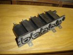
PS: Again referring to the OP's photo, the inner box, without a cover, would need only a total of 4 or 5 slots, each cut from the terminal hole to the front edge of the box. But if the cover plate is added and is also ferrous, it would end up bridging those slots magnetically and causing problems. The issue is not circulating currents, but rather magnetic fields with hysteresis losses.
Using an aluminum cover plate would fix that.
PPS: And finally, mounting each individual terminal on a
separate non-ferrous plate would not be sufficient if each conductor still passed through a separate larger hole in the ferrous enclosure.