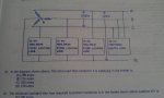
heater load calculation

Status
Not open for further replies.
Location
OBX, NC.
Review the question attached, please share the best method of calculation you are familiar with..
 

Attachments

  • IMAG0399.jpg
    IMAG0399.jpg
    145.8 KB · Views: 0
Last edited:

JoeStillman

Senior Member
Location
West Chester, PA
You could think of this a two balanced 3? loads; one at 30 kW (the heater) and one at 45kW (the lights.)

Conversely, assuming the 30 kW load is balanced, you could say the single-phase load on ?A is 15 kW (lighting) plus 10 kW (heat).

The formula for 3? amps is (kW/Vx1.732)x1000 where V is the line-to-line voltage. For 1? amps, leave out the square-root of three and use the line to neutral volts.

The answer is inside your own head. Just find a way to let it out.
 

Julius Right

Senior Member
Occupation
Electrical Engineer Power Station Physical Design Retired
There are some misunderstandings:
1) It is noted : 21.In the diagram shown above: The total load that conductor A is supplying in the feeder is:
(A)208 amps (B)216 amps(C)260 amps(D)270amps.
what is "conductor A" then and what is phase (D)-could be N?
2) If the heater is "pure resistance" so its rated current will be 83.27 A symmetrical in all three phases.
That means the power factor-cosfi-in the three nonlinear loads will be different.
3) it could be a lot of harmonics in these loads so the calculation is impossible unknowing this.
I did a calculation neglecting the harmonics and this is the result:
using the general equation:
IA=Iheater+IkwA*(cos(fiA)+j*IkwA*sin(fiA) where: IA=208;IB=216;IC=260; ID=270 A
IkwA=actual current module of single phase load in A.
Iheater=83.27 A
I got IkwA=-Iheater*cos(fiA)+sqrt(IA^2-Iheater^2*sin(fiA)^2)
In order to state the pf[cos(fi)] you may change the pf while the power of unit will be 15 kw.
In order to get ID you have to recalculate the real and imaginary parts of the currents using the angle acos(fiA);-(acos(fiB)+2*PI()/3);-(acos(fiC)+4*PI()/3)
I got for the 208,216 and 260 pf 1,0.91,0.63 and the currents[separately for single phase units]:
124.73,137.44,199.37 A.
But the I(D)=-SUM(IA:IC) it is only 135.6 A.
I think the harmonics have a function here.
 

GoldDigger

Moderator
Staff member
Location
Placerville, CA, USA
Occupation
Retired PV System Designer
The answer is C.
15kw/120=125amp
30kw/360=83amps
125 +83= 208 amps
208*1.25=260 amps

Is that what you are looking for?

If the question is asking for the RMS current, then the fact that the lighting load is non-linear does not enter into the calculation, but the displacement power factor, if it is low, certainly will.
I think that the "non-linear" was inserted in preparation for a later question about the neutral current ampacity needed, but conveniently ignored for the first question. :thumbsdown:
 
Location
OBX, NC.
SO FAR NO CORRECT ANSWERS..

SO FAR NO CORRECT ANSWERS..

The test booklet I have from the state of NC. gives the answer to be A.. I really appreciate the attempts.. This is a tough one. Maybe the answer is not the best answer but is applied to the best answer provided..?
Thanks Again...
 
Location
OBX, NC.
Based on the answer givenin the test book and the formula given in post # 2, I was able to

30kw =30000w

30000w / (208v * 1.73) = 83.3A

15kw=15000w

15000w/120v=125A

Add both ampacities together for a total of 208.

Needed formula for 3 phase load is............. Watts / (volts * 1.73) =Amps
" " " single phase load...... Watts / Volts =Amps
 

dkidd

Senior Member
Location
here
Occupation
PE
Another way to look at it is that A is serving 1/3 of 30KW plus 15KW for a total of 25KW.

25KW/120v=208A.
 

Julius Right

Senior Member
Occupation
Electrical Engineer Power Station Physical Design Retired
So, this was a joke for Elementary School students. I don't think it was funny. Sorry!:happyno:
 

gar

Senior Member
Location
Ann Arbor, Michigan
Occupation
EE
131002-1014 EDT

The answer from the book is almost certainly wrong. It would be correct if the non-linear loads were resistors, but by the non-linear statement they are not. My guess is possibly 260 A, but there is not enough information.

The load current of a 15 kW non-linear load at 120 V is something greater than 125 A RMS, and non-sinusoidal. So without other information it is a guess. But the power factor of a non-linear load is not likely to be very good. What really needs to be known is the waveform of the current of the sine wave resistive load plus the non-linear load. Then this waveform needs to be analyzed to determine its RMS value. This analysis is beyond the background of a typical electrician.

.
 

kwired

Electron manager
Location
NE Nebraska
The answer is A (with an "or greater attached to it) - until enough details of the non linear load is given to determine what is actually there.

What kind of person was the question written for? (apprenticeship progressive testing, journeyman exam question, engineering student, EE licensing testing, etc.?
 

gar

Senior Member
Location
Ann Arbor, Michigan
Occupation
EE
131002-1245 EDT

A simple experiment. One 26 W CFL (non-linear load) and one 15 W incandescent (resistive load).

123 V and a Kill-A-Watt instrument.

Actual measurements.

CFL --- 0.27 A, 23.4 W, 33.8 VA, 0.69 PF
15W -- 0.12 A, 15.3 W, 15.3 VA, 1.00 PF

Both -- 0.37 A, 38.6 W, 45.9 VA, 0.84 PF


Conclusions:

= 38.7 vs 38.6 . Fairly close.

Voltage varied somewhat and CFL has some instability. But, it is clear that you can not calculate total current from the 23.4/123 = 0.19 and add 0.12 and get 0.37 . Also, you can not just add 0.27 and 0.12 and say these are the total current. You must know the waveform and calculate from the waveform.

It is interesting that :
216/208 = 1.04
260/208 = 1.25
270/208 = 1.30

and
(0.27+0.12)/( (23.4+15.3)/123 ) = 0.39/0.31 = 1.26

This supports my guess that 260 might be a possible answer. When guessing I was not expecting to be that close to some actual measurement.

.
 
Status
Not open for further replies.
Top