Bearing Damage

Status
Not open for further replies.

captainwireman

Senior Member
Location
USA, mostly.
I attended a motor calculations upgrade class recently. The instructor showed me a standard ball bearing where the race had overlapping half circle wear marks very similar to two side by side completely flat tig welding beads all around the race about one quarter the size of the ball. He said this was due to a problem with the motor not being rated for a VFD system. Is anyone familiar with this and could you give a complete explanation of why this occurs?
 

iwire

Moderator
Staff member
Location
Massachusetts
I have seen it first hand on 500 HP motors, I worked with the motor company swapping them out with ceramic lined bearings so they were non-conductive

I spent a ton of time doing whatever a gaggle of engineers said while they tried to pin down the problem. These motors were VFD rated.

All that said I do not know the true cause and the proper fix. The motor guys said the ceramic bearings were just going to relocate the problem not eliminate it.

At full speed we had 17 to 20 amps of current trying to pass through the bearings.
 

GoldDigger

Moderator
Staff member
Location
Placerville, CA, USA
Occupation
Retired PV System Designer
I attended a motor calculations upgrade class recently. The instructor showed me a standard ball bearing where the race had overlapping half circle wear marks very similar to two side by side completely flat tig welding beads all around the race about one quarter the size of the ball. He said this was due to a problem with the motor not being rated for a VFD system. Is anyone familiar with this and could you give a complete explanation of why this occurs?

The problem is most likely that the sharp edged voltage waveforms from the VFD induced harmonic currents that ended up flowing through the bearings between the rotor and the motor frame.
You can find the subject discussed in some older threads on the Forum and some of the posts have references to papers on the subject.

This, as well as insulation breakdown problems, can be prevented by proper motor design with that in mind, and you may be able to get an old motor to survive well enough by adding in load reactors between the VFD and motor.

From what I understand and cannot explain very well the rotor is not symmetric from end to end at higher frequencies and the result is somewhat analogous to the harmonic currents in the neutral wire of a balanced wye with non-linear loads. (With the exception that unlike the neutral of a wye, the bearings were never expected to carry any current at all.)
 
Last edited:

Besoeker

Senior Member
Location
UK
I have seen it first hand on 500 HP motors, I worked with the motor company swapping them out with ceramic lined bearings so they were non-conductive

I spent a ton of time doing whatever a gaggle of engineers said while they tried to pin down the problem. These motors were VFD rated.

All that said I do not know the true cause and the proper fix. The motor guys said the ceramic bearings were just going to relocate the problem not eliminate it.

At full speed we had 17 to 20 amps of current trying to pass through the bearings.
According to the Gambica report I have on the subject, inverter induced capacitive currents cause bearing problems. High dv/dt .

Insulated or ceramic bearings is one of the mitigating measures suggested.
 

iwire

Moderator
Staff member
Location
Massachusetts
According to the Gambica report I have on the subject, inverter induced capacitive currents cause bearing problems.

Insulated or ceramic bearings is one of the mitigating measures suggested.

Keep in mind this was number of years ago. It was a thorny issue as two well known engineering firms had their hands on the design resulting in much finger pointing. A third firm was brought in and that resulted in a total of at least 20 people on site tying to nail it down.

The issue with the ceramic bearings was simply the fact that the motors where directly coupled to the load they drive so now the current would want to go through the bearings supporting the driven equipment.

They had us put grounding brushes on the motor shaft but I have no idea how the electrons knew they where all supposed to go through the brush and none through the driven equipments bearings.

I don't know what they eventually did. I moved on before an answer was found.
 

Jraef

Moderator, OTD
Staff member
Location
San Francisco Bay Area, CA, USA
Occupation
Electrical Engineer
The phenomenon is real, if you do a search on "bearing EDM damage"+ VFD you should find numerous papers on it, most of which are good for helping you fall asleep at night.

Reader's Digest version:
The fast rise time of the DC pulses that make up the PWM "pseudo AC" current going to the motor from the VFD, can under some circumstances cause a capacitive and/or inductive coupling effect between the stator and the rotor; the two separate elements can charge up like the plates of a capacitor. That means there is a voltage across them and that voltage charge, although in the millivolt range, can build up to the point where it exceeds the dielectric strength, or the insulating quality, of the lubricant film in the bearings. The voltage then flows from the rotor to the stator because the stator is grounded, passing through the bearings and races. At a microscopic level, that voltage is just like an EDM system (Electric Discharge Machining, hence the name of the phenomenon) and the tiny little discharges make a tiny little pit in the races, like a welder might. The bearings then roll over those pits, and they become an easier point to discharge next time. Repeat roughly 2.5 million times per day, the cumulative damage to the races starts to look like a washboard and the bearings become damaged as they fall into and out of those depressions. The worse it gets, the faster it happens, so critical failure is often rapid.

There are numerous things that cause and affect the severity of this, there are numerous things that can be done about it, all with good and bad points. One method is to use grounding shaft bushings on the motor, which gives the charge and EASIER path to ground than through the bearings (addressing the "how do the electrons know?" issue, search for "Aegis shaft grounding" for more info). But they become a wear part that has to be monitored and replaced periodically. Another method is to use non-conductive bearing races, i.e. the ceramic mentioned earlier, but that doesn't really address the problem, it addresses the symptom. I've also heard tell that the isolated bearing approach only works if designed into the motor in the beginning, that retrofitting them is not very effective. I couldn't tell you why, however it is becoming a common approach in "Inverter Duty" motor designs. A third approach is to eliminate the CAUSE of it in the first place, the steep wave fronts of the PWM pulses. DV/DT filters, or "Sine Wave" filters, between the VFD and the motor is one way to do that. You are adding inductance, which adds what is called the "Inductive Time Constant" to the change in voltage of those pulses, which reduces the capacitive effect at the motor end. Plus you are filtering out the peaks of any spikes that happen as a result of "standing waves", another issue that contributes not only to this, but also to motor winding insulation breakdown (typical of 380V and up drives). But DV/DT filters then can affect the motor circuit and the performance of critical Vector Control applications. Keeping the motor as close to the drive as possible also helps a little, but is not always practical. Using what is called "VFD cable", which is shielded and grounded at both ends, also seems to help some by reducing the capacitive coupling taking place in the motor cables that makes it worse. In places outside of North America where the use of this cable is more common or even mandated, they don't have this problem as much.

The best thing is not to assume any one solution is the cure-all because the problem is not always caused by the same thing, but rather to address which problem might be giving you the issue, then addressing THAT with one of these solutions. This presentation is one of the best and simplest to understand on the subject (the author happens to be a friend of mine). At the very end he is making a case for a little meter device he is selling, but the treatment of the causes and solutions is as good as any I have seen since he is not biased by wanting to sell one solution or another.
www.gke.org/.../files/EDM Physics and Reality 1.pdf?
 

Besoeker

Senior Member
Location
UK
Keep in mind this was number of years ago. It was a thorny issue as two well known engineering firms had their hands on the design resulting in much finger pointing. A third firm was brought in and that resulted in a total of at least 20 people on site tying to nail it down.
Reminds of an old saying.
A camel is a horse designed by a committee.
Having been in the drives field for a good many years, I'm a bit familiar with the situation you mention.

The issue with the ceramic bearings was simply the fact that the motors where directly coupled to the load they drive so now the current would want to go through the bearings supporting the driven equipment.
Yes, makes sense. The Gambica report mentions that too.

They had us put grounding brushes on the motor shaft but I have no idea how the electrons knew they where all supposed to go through the brush and none through the driven equipments bearings.
I don't know what they eventually did. I moved on before an answer was found.
Again, from the report, grounding brushes is not considered to be very effective which mirrors your thoughts.

I've mentioned previously, possible a couple of years ago, that that I'd heard of bearing problems related to VSDs but not personally come across it. Possibly different installation practices.
On this forum I've read about special VSD cables. Maybe that could have been the answer?
 

GoldDigger

Moderator
Staff member
Location
Placerville, CA, USA
Occupation
Retired PV System Designer
On this forum I've read about special VSD cables. Maybe that could have been the answer?
Special VSD cables are generally used to deal with insulation damage from dV/dt effects in ordinary cables and with radiated interference that affects other nearby circuits. I have not heard them described as helpful in protecting the motors.
If you use single wire conductors, the magnetic forces on them can be substantial too.
 

GoldDigger

Moderator
Staff member
Location
Placerville, CA, USA
Occupation
Retired PV System Designer
Why would harmonic spikes or for that matter any voltage passing through the bearing races and balls cause uneven wear?
Voltage passing through the bearing races would not be problem. But current passing through the lubricated rolling contact between the balls and the races will create thousands of tiny arcs per minute which pit and erode away the metal of the race and the balls themselves.
 

iwire

Moderator
Staff member
Location
Massachusetts
Why would harmonic spikes or for that matter any voltage passing through the bearing races and balls cause uneven wear?

I wish I had taken a picture of the damage I saw, it had a very distinct pattern and had some very deep groves in the races perpendicular to the rollers.

Before we took the motors off line it had sounded like someone had dumped a bag of pebbles into the bearings. It was not just loud, it was actually scary to be near them. It sounded like they were going to blow apart.

All four 500 HP motors had the same exact damage.
 

SceneryDriver

Senior Member
Location
NJ
Occupation
Electrical and Automation Designer
Could you kindly explain what dv/dt means?

Change (delta) in voltage / Change (delta) in time

A measure of the risetime of a signal.

Higher dv/dt values can lead to transmission line effects - http://en.wikipedia.org/wiki/Transmission_line - where standing waves can actually lead to a doubling (or higher) of the voltage produced by the drive. 480v motors may actually see up to 1200v spikes. If not properly insulated and designed for, these spikes can quickly lead to motor insulation and wire insulation breakdown and failure.

Also see:
http://en.wikipedia.org/wiki/Variable-frequency_drive#Long_lead_effects

http://en.wikipedia.org/wiki/Shaft_voltage


SceneryDriver
 
Last edited:

iwire

Moderator
Staff member
Location
Massachusetts

Yes, but much much deeper, more uniform and further apart.

A few pics

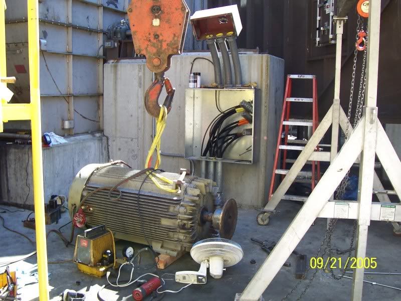
Here we have the motor removed and the mechanics are having a hard time pulling the coupling off. They had heated it but had to stop and cool it back off for a second attempt

2ea6f5c0.jpg


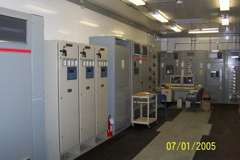
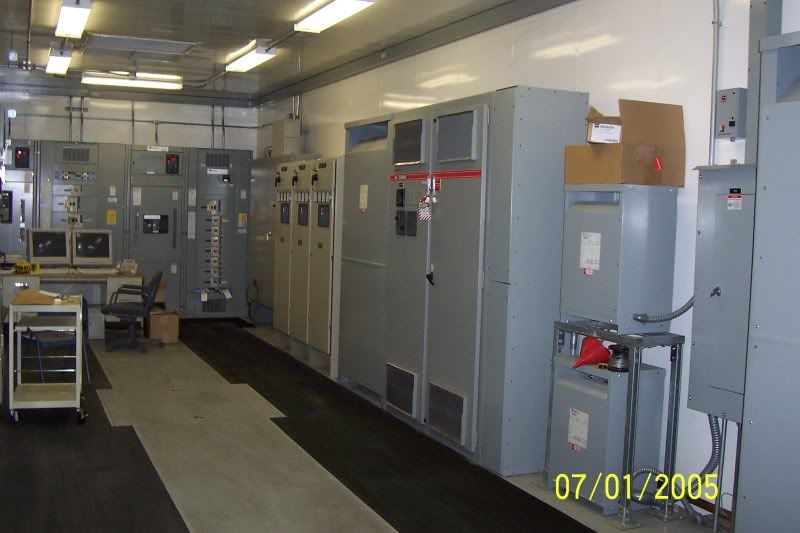
The control room, VFDs, high voltage supplies, MCC etc. I think the VFDs were Cutler Hammer.
7d27e398.jpg


79ecc683.jpg


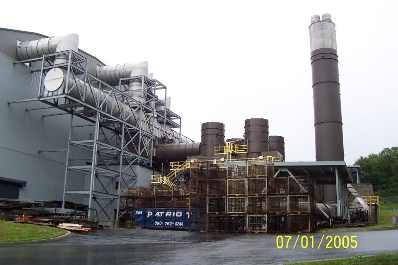
Here is an overview, its a wet electrostatic precipitator for a burn testing building

aed891c1.jpg
 

Besoeker

Senior Member
Location
UK
Special VSD cables are generally used to deal with insulation damage from dV/dt effects in ordinary cables and with radiated interference that affects other nearby circuits. I have not heard them described as helpful in protecting the motors.
Dv/dt effects can and sometimes do damage motor insulation. I've come across a few of those. In one case 800kW motors were suffering insulation failures after about a month in operation.
And dv/dt effects result in capacitive currents to the motor shaft via the bearings.
 

Besoeker

Senior Member
Location
UK
Yes, but much much deeper, more uniform and further apart.
Yes, I can imagine that it might manifest itsef differently on different motors.
I don't know the provenance of the pic I posted. It just came out of that Gambica report.
The information on the problem generally suggests that it relates to larger machines. Whatever larger is taken to mean.


A few pics

Here we have the motor removed and the mechanics are having a hard time pulling the coupling off. They had heated it but had to stop and cool it back off for a second attempt

The control room, VFDs, high voltage supplies, MCC etc. I think the VFDs were Cutler Hammer.

Here is an overview, its a wet electrostatic precipitator for a burn testing building

Pics appreciated, thanks - to keep the post my post size down, I haven't repeated them in mine.

Fleshes out the story. The fan blowing on the coupling......
The control room is tidier than some I've seen.
 
Status
Not open for further replies.
Top