Load- or line side tie?

Status
Not open for further replies.

Zee

Senior Member
Location
CA
Hey all,

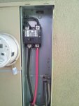
How specifically would you tie into this panel in a Code-compliant manner?
I've done some line side ties (AKA supply side) but the specifics here interest me:
~ Can i land my wires in the line side terminals of the Main breaker?
Cutler-Hammer, Catalog no. BW2200.
~ How can i find out if above is rated for "double lugging", 2 wires in terminal lugs?
~ Has anyone tied into the meter lugs before?

Details:
1. Subpanel more or less inaccessible inside house.:happyno:
2. I beleive this AHJ does not allow load side taps....will check.
3. I got the other stuff; 60A wiring and disco minimum, with fuses rated for my inverter (sma sb5000tl-us, rated ac amps: 22), as close as possible, steel conduit if possible.
4. Splitbolts don't fit on line side conductors, as seen on photo.
 

Attachments

  • 20131029_153040.jpg
    20131029_153040.jpg
    136.6 KB · Views: 1
Last edited:

jaggedben

Senior Member
Location
Northern California
Occupation
Solar and Energy Storage Installer
Assuming the conductors are rated 200A, then in my opinion a load side tap is compliant. But if you can't convince the AHJ of that, then the most legit way is probably to add a new 200A subpanel right next to that panel. The new sub would contain another 200A breaker to feed the existing sub, as well as your solar breaker. You'd probably have to splice that existing sub feed inside the panel in your photo (e.g. w Polaris type) but I don't see any difficult complying with 312.7 and 312.8.

Finding equipment that will allow a 200A sub breaker may be difficult, this sort of thing is admittedly easier for a 100A service. Sometimes a service upgrade can be cheaper/easier.
 

Zee

Senior Member
Location
CA
Thanks Jben,
I really need to explore line side options. Anyone?

If not possible, i'll pay for a service upgrade to a "solar ready" 200A panel.
 

anndee4444

Member
Location
California
Thanks Jben,
I really need to explore line side options. Anyone?


While technically a load side connection, I suggest you look closely at the 120% rule. Specifically this: "sum of the ampere ratings of the overcurrent protection supplying power to the busbar or conductor shall not exceed 120% the ampacity of the busbar or conductor"

There are a couple of ways to look at this, but the way I see it is that this panel does not apply to the 120% rule (since if it had a busbar, there would only be on ocpd supplying power to it: the PV breaker). If the jurisdiction wants to hold you to the rating on the conductors (which was removed for 2014), upgrading them should not be an issue.
 

BillK-AZ

Senior Member
Location
Mesa Arizona
I had a related challenge with a 600A 120/208V 3-ph no main device service entrance that would only accept six switches and all were in use. A supply side connection would exceed the six switch rule. The PV required 120A and only 200A switches could be used.

We upgraded the cable on a 200A fused switch to 267A at the temperature derate for the terminals, installed a Boltswitch 200A fused pullout for the existing load cable, and a 200A fused safety switch disconnect for the PV. Insulation piercing connectors were used for the 3-way connection, there was room in a wireway.

The same basic procedure would work here by applying the 120% rule to the cable out of the main device, adding a pullout for the existing load, and fused disconnect switch for the PV inverter. There are details such as wire bending radius, terminal sizes, interrupt ratings, etc. to pay attention to.
 

Zee

Senior Member
Location
CA
BILLK-AZ,
Here,
A. only line-side connections,
B. or load-side connections - WITH A BREAKER - are acceptable! (No taps or splices allowed, unless line side.)

A. Line side is out:
1. No room on service entrance conductors for splice.
2. The line side, terminal lugs of the breaker are not permissible to "double lug" ( add another , PV conductor to) - per mfctr (cutler hammer), and AHJ.

B. Load side:
This is where i hope for a solution, as in a new sub-panel (ala Jben). The problem is getting my (N) 2p30A PV breaker to be positioned "opposite feed".
Is there a 200 Amp load center that can have a 200Amp sub feeder breaker plugged onto its load side bussing?
That is the solution. That is what i need so i can have my PV breaker in a position to not violate the 120% rule, ie opposite the feed.

Anndee4444, Yes , we always consider the 120% rule on every job. Upgrading the conductors is an issue.


I am really beating a dead horse here, I know, as no-one has come up with a workable solution...I realize I can do a service upgrade and then that new panel can have the option to add a breaker or do a line side tie. But i do not yet want to accept that i have to junk a perfectly good 200A meter/main in order to tie in the PV.:cry: But i may have to.
 
Last edited:

GoldDigger

Moderator
Staff member
Location
Placerville, CA, USA
Occupation
Retired PV System Designer
BILLK-AZ,
Here,
A. only line-side connections,
B. or load-side connections - WITH A BREAKER - are acceptable! (No taps and fused discos, unless line side.)

A. Line side is out:
1. No room on service entrance conductors for splice.
2. The line side, terminal lugs of the breaker are not permissible to "double lug" ( add another , PV conductor to) - per mfctr (cutler hammer), and AHJ.

B. Load side:
This is where i hope for a solution, as in a new sub-panel (ala Jben). The problem is getting my (N) 2p30A PV breaker to be positioned "opposite feed".
Is there a 200 Amp load center that can have a 200Amp breaker plugged onto its load side bussing?
That is teh solution. That is what i need so i can have my Pv breaker opposite it.

Anndee4444, Yes , we always consider the 120% rule on every job. Upgrading the conductors is an issue.


I am really beating a dead horse here, I know, as no-one has come up with a workable solution...I realize I can do a service upgrade and then that new panel can have the option to add a breaker or do a line side tie. But i do not yet want to accept that i have to junk a perfectly good 200A meter/main in order to tie in the PV.:cry: But i may have to.

As long as you use wiring rated for 200A, it will be protected by the 200A main in the meter-main. So a T-connector on the load side of your existing 200A main would not be a tap. Run that to an MLO load center with the PV breaker at the opposite end of the bus from the main lugs and you should be OK.

If necessary you can increase the size of the conductors to the new panel so that that conductor also is loaded within the 100% not 120% rule.

I do see your potential problem that the actual load breakers in the existing main panel will be on the same side of both the main and the PV input. If there is any way you can increase the size of the conductors from the meter main to the existing main panel (so that they are rated for 100% of main + PV instead of just 200A), then you should no longer be limited by the "opposite end" rule.
 

Smart $

Esteemed Member
Location
Ohio
...

I am really beating a dead horse here, I know, as no-one has come up with a workable solution...I realize I can do a service upgrade and then that new panel can have the option to add a breaker or do a line side tie. But i do not yet want to accept that i have to junk a perfectly good 200A meter/main in order to tie in the PV.:cry: But i may have to.
Can you make the taps on the meter side?

...or replace the conductors from the meter terminals to customer side with longer ones, so you have enough length to make a T-tap on the customer side and re-feed the existing main?

You'd pull the meter (or have the POCO pull it) to make the line-side taps anyway, wouldn't you?
 

jaggedben

Senior Member
Location
Northern California
Occupation
Solar and Energy Storage Installer
Can you make the taps on the meter side?

...or replace the conductors from the meter terminals to customer side with longer ones, so you have enough length to make a T-tap on the customer side and re-feed the existing main?

You'd pull the meter (or have the POCO pull it) to make the line-side taps anyway, wouldn't you?

Usually the conductors from the meter to the main breaker in a combo are factory installed and it would be a violation of the listing to do anything to them. Then again, it might be worth asking the manufacturer's opinion in this case. And the AHJ may or may not care.
 

Smart $

Esteemed Member
Location
Ohio
Usually the conductors from the meter to the main breaker in a combo are factory installed and it would be a violation of the listing to do anything to them. Then again, it might be worth asking the manufacturer's opinion in this case. And the AHJ may or may not care.
I thought about that... noteworthy... and exactly as you stated. Just forgot to mention it.

I can see listing issue being more prevalent if we were talking busbar, but in this case we're just talking plain ol' run-o'-the-mill, insulated conductor (though of the appropriate type, of course ;)).

Also, listing doesn't automatically mean approved by AHJ... just as modified can be approved by AHJ... same as you noted, just worded differently :cool:.
 

Zee

Senior Member
Location
CA
Thanks Golddigger,
Yes, the issue is that the 200 and 30 can add, thus exceeding the 200A (E) feeder wire's ampacity.
Re. upgrading the feeder wire...it's 4/0 SE cable (the heavy romex type stuff) inside walls, up several stories.....no way!

Thanks Smartmoney,
Yes, replacing the short and tightly bent conductors from meter to line side of main breaker would physically work (to allow tap) ...........it gets into violating the listing of the combination meter/main, etc. Stuff I do not know much about - but the inspector does....:weeping:
Yeah, you are right pulling the meter is no problem - and exactly what i would do in order to tap line-side.

Thanks JaggedBen,
Yeah, replacing conductors as above may be an option in the future. I do seriously doubt any mfctr would say yes, though. Why would they, they could only stand to lose.
On the other hand: Let's put it this way, if there were no AHJ, i would do it in a heartbeat: i know my work and would use the right wire. Come to think of it, w/o the photo above....who would know there hadn't always been nice big, pig-tailed loops on the SE conductors...???:roll:
~~~~~~~~~~~~~~~~~~~~~~~~~~~~~~~~~~~~~~~~~~~
I've learned a lot for future reference, that 'll be mighty handy!

Right now i think i got it:
I heard of a 200 AMP branch circuit breaker that i can add to a 200 amp panel!
Turns out, Square D makes it in both HOM and QO. Takes 4 spaces (instead of 2).
This'll plug onto any HOM or QO busbar. So i'll take the (E) 4/0 sub-panel feeder conductors from the (E) 200A main breaker and feed them off of this. Place this (N) 200A breaker in a new subpanel (in the middle of the busbar somehwere) and plug my (N) 2p30A PV Breaker on the bottom.
That should meet 120% rule and "opposite feed" section of said rule.
The things solar will make you do.........:p
 
Last edited:

acrwc10

Master Code Professional
Location
CA
Occupation
Building inspector
Thanks Golddigger,
Yes, the issue is that the 200 and 30 can add, thus exceeding the 200A (E) feeder wire's ampacity.
Re. upgrading the feeder wire...it's 4/0 SE cable (the heavy romex type stuff) inside walls, up several stories.....no way!

Thanks Smartmoney,
Yes, replacing the short and tightly bent conductors from meter to line side of main breaker would physically work (to allow tap) ...........it gets into violating the listing of the combination meter/main, etc. Stuff I do not know much about - but the inspector does....:weeping:
Yeah, you are right pulling the meter is no problem - and exactly what i would do in order to tap line-side.

Thanks JaggedBen,
Yeah, replacing conductors as above may be an option in the future. I do seriously doubt any mfctr would say yes, though. Why would they, they could only stand to lose.
On the other hand: Let's put it this way, if there were no AHJ, i would do it in a heartbeat: i know my work and would use the right wire. Come to think of it, w/o the photo above....who would know there hadn't always been nice big, pig-tailed loops on the SE conductors...???:roll:
~~~~~~~~~~~~~~~~~~~~~~~~~~~~~~~~~~~~~~~~~~~
I've learned a lot for future reference, that 'll be mighty handy!

Right now i think i got it:
I heard of a 200 AMP branch circuit breaker that i can add to a 200 amp panel!
Turns out, Square D makes it in both HOM and QO. Takes 4 spaces (instead of 2).
This'll plug onto any HOM or QO busbar. So i'll take the (E) 4/0 sub-panel feeder conductors from the (E) 200A main breaker and feed them off of this. Place this (N) 200A breaker in a new subpanel (in the middle of the busbar somehwere) and plug my (N) 2p30A PV Breaker on the bottom.
That should meet 120% rule and "opposite feed" section of said rule.
The things solar will make you do.........:p

You could do a load calc and down size the main OCPD.
 

Smart $

Esteemed Member
Location
Ohio
...

Thanks Smartmoney,
Yes, replacing the short and tightly bent conductors from meter to line side of main breaker would physically work (to allow tap) ...........it gets into violating the listing of the combination meter/main, etc. Stuff I do not know much about - but the inspector does....:weeping:

...
Have you looked into double/dual lugs at the meter end of the conductors, or tapping the conductors on the meter side of the combo (such as with insulation-piercing tap connectors; not a fan, but if all else fails...)?

Ultimately, have you actually asked the AHJ if there is a method to tap the service conductors that'll meet their approval?
 

Zee

Senior Member
Location
CA
Have you looked into double/dual lugs at the meter end of the conductors, or tapping the conductors on the meter side of the combo (such as with insulation-piercing tap connectors; not a fan, but if all else fails...)?

Ultimately, have you actually asked the AHJ if there is a method to tap the service conductors that'll meet their approval?

Thanks,
Nope, i assumed they would not allow me to do anything in the meter enclosure.
I should ask them. Next time. The new sub-panel will work now.
 

Zee

Senior Member
Location
CA
I'll be feeding 200Amps into this new 200A rated sub-panel.

I'll be feeding it with 2 @ 3/0 hot wires from the main panel and a #6 EGC from the main panel - thru a 2" offset nipple.

Can i run a single 3/0 NEUTRAL conductor from the (E) main panel's neutral bar to the neutral in the new sub-panel?
(instead of running in and out with the neutral)
 

jaggedben

Senior Member
Location
Northern California
Occupation
Solar and Energy Storage Installer
Just to be clear, the hots are returning to the existing subfeed via the same nipple, right? So you're proposing that the wires through the nipple would be four hots (two in each direction) and one neutral, right?

The code section at issue is 300.20.

If not for the solar, I'd say 300.20 is satisfied if you do it as described above, because any hot currents flowing to the existing sub cancel out through the nipple, and you don't have a problem.

However, since you're going to be adding the solar to the sub, that throws me for a bit of a loop. It's that whole thing of where the unbalanced current comes from and goes to with a utility interactive inverter. Until I see or draw out a diagram I can't say for certain that all the currents in the nipple would cancel out.

And just to complicated it (maybe) ... :lol: ... should we assume it would be possible to have an additional load in the sub as well?
 

ggunn

PE (Electrical), NABCEP certified
Location
Austin, TX, USA
Occupation
Consulting Electrical Engineer - Photovoltaic Systems
I'll be feeding 200Amps into this new 200A rated sub-panel.

You know that the 200A in the subpanel counts toward the 120% rule in the main panel, don't you? The main needs to be 1000A if its OCPD and busbar ratings are the same.
 

jaggedben

Senior Member
Location
Northern California
Occupation
Solar and Energy Storage Installer
You know that the 200A in the subpanel counts toward the 120% rule in the main panel, don't you? The main needs to be 1000A if its OCPD and busbar ratings are the same.

I think you read too fast. The 200A is the utility feed. The inverter output is 22A.
 

Zee

Senior Member
Location
CA
Thanks Jben,
Just to be clear, the hots are returning to the existing subfeed via the same nipple, right? So you're proposing that the wires through the nipple would be four hots (two in each direction) and one neutral, right?
Yes. (and a #6 egc of course)
The code section at issue is 300.20.
Oh, OK.
If not for the solar, I'd say 300.20 is satisfied if you do it as described above, because any hot currents flowing to the existing sub cancel out through the nipple, and you don't have a problem.

However, since you're going to be adding the solar to the sub, that throws me for a bit of a loop. It's that whole thing of where the unbalanced current comes from and goes to with a utility interactive inverter. Until I see or draw out a diagram I can't say for certain that all the currents in the nipple would cancel out.
EXACTLY what i cannot get my head around.
And just to complicated it (maybe) ... :lol: ... should we assume it would be possible to have an additional load in the sub as well?
DEFINITELY. Good Q. This will be a big, 30 space panel. WIth a 200 A load breaker and a 30 A "load" aka PV breaker (22A @ 125%) - for starters.
 
Status
Not open for further replies.
Top