Thanks I looked up that link and it gave me all the information I need to file a complaint. I'm not sure I want to file a complaint because we have to work with the POCO all the time and it would seem it could make things even tougher then they already are. I don't understand why it's always so difficult to deal with them and they always push any issue off to someone else. Do you know or have you ever filed a complaint through the UTC? I could see it being some dog and pony show where I get forced to spend a lot of time into this matter and then nothing changes as far the issues I have to deal with.
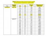
I got another response from their engineering dept. which is why off and I don't know why these don't use the actual specs of the wire size and distance because they have this information and also I have given it to them. The gear is feed with parallel 750MCM AL that is 15' runs. When you have parallel sets or more then one run you just take the distance of one conductor, is that correct? Does anyone know what "C" & "f" & "M" values stand for?
Phase-Phase Voltage (V) 208
Transformer Rating (VA) 500,000
Transformer Full Load (A) 1,388
Transformer Impedance (%) 2.30
Transformer Multiplier 43.48
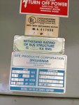
Short Circuit Current at Transformer's Secondary Bus (A) 60,344
Transforemer R/X 0.20
Conductor (kcmil) 500
Conductor Length (ft) 100
Conductor Resistance (Ohm/1000ft) 0.04
Conductor Reactance (Ohm/1000ft)
"C" Value 21,391
"f" Vaule 2.35
"M" Value (Multiplier) 0.30
Short Circuit Current at Gear (A) 18,018
So here's what I'm coming up with using there same excel spreadsheet:
Phase-Phase Voltage (V) 208
Transformer Rating (VA) 500,000
Transformer Full Load (A) 1,388
Transformer Impedance (%) 2.30
Transformer Multiplier 43.48
Short Circuit Current at Transformer's Secondary Bus (A) 60,344
Transforemer R/X 0.20
Conductor (kcmil) 750 ------------------------This doesn't change anything
Conductor Length (ft) 18
Conductor Resistance (Ohm/1000ft) 0.03 -------This figure doesn't change any values either
Conductor Reactance (Ohm/1000ft) ------------This was left blank
"C" Value 21,391 ---------------------------------------\
"f" Vaule 0.42 --------------------------------------------> I'm not sure what these numbers are related to can someone help me?
"M" Value (Multiplier) 0.70 ------------------------------/
Short Circuit Current at Gear (A) 42,411 --- The gear is rated at 42k
Thanks for all the help