sparktrition
Member
- Location
- Colorado
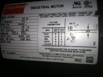
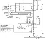
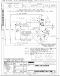
I replaced a 220v hanger door motor with a Dayton5k673bb. The old motor had a two and three wire SO cord feeding it from a 2 contactor, 2 limit switch, 24v coil system. I don't understand how to reverse this motor using the five wires coming from my up and down contactors.
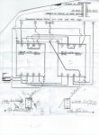
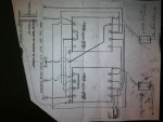
Part of the problem is the contactor schematic is not in a ladder diagram form. I have left the contactors operating in the same exact way as they are in the diagram. I have been able to get the motor to operate in both directions, but i had to swap the red and black wires manually on the motor. How can i achieve this process using the five wires with the 2 contactors.
Any help with this is much appreciated.