NEC 20011; 300.20 Induced Currents in Ferrous Metal Enclosures

Status
Not open for further replies.

rayp1

Member
Location
Phoenix, Az, USA
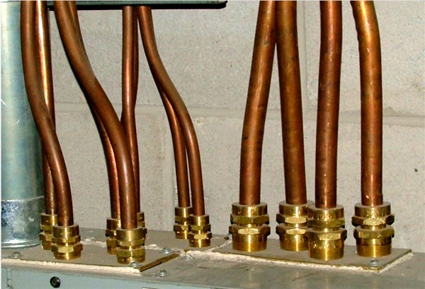
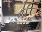
Situation: Cable types are MC single conductor with exterior sheath coat installed in cable tray than secured to the metal enclosure of a dry type transformer. (44 TX's!). Individual TnB fittings are used for each phase and neutral. See attached picture. Inspector sited 300.20 violation, induced current-resulting in excessive heat issue.

Question:
a. How does the induced currents occur with the individual grounds connected to the transformer bus?

b. Any evidence to debate the violation?
 

Attachments

  • TX in, out.jpg
    TX in, out.jpg
    127.8 KB · Views: 5

don_resqcapt19

Moderator
Staff member
Location
Illinois
Occupation
retired electrician
The grounds do not change the magnetic fields around the conductors. The magnetic fields around the power conductors are what causes the inductive heating where there is ferrous metal surrounding individual conductors.
 

Smart $

Esteemed Member
Location
Ohio
It's not system current but rather hysteresis current (sometimes known as eddy current) caused by the electric field around each current-carrying conductor. The eddy current travels in the enclosures ferrous metal in a circular pattern around each penetration. Where currents oppose each other, heat is generated. Cutting slots between the penetrations force any resulting current to flow completely around all the penetrations of the circuit. The majority of eddy current will be mitigated.

Another option is to cut out the penetration area and replace with non-ferrous metal.
 

rayp1

Member
Location
Phoenix, Az, USA
Further details.

Further details.

It's not system current but rather hysteresis current (sometimes known as eddy current) caused by the electric field around each current-carrying conductor. The eddy current travels in the enclosures ferrous metal in a circular pattern around each penetration. Where currents oppose each other, heat is generated. Cutting slots between the penetrations force any resulting current to flow completely around all the penetrations of the circuit. The majority of eddy current will be mitigated.

Another option is to cut out the penetration area and replace with non-ferrous metal.
***********

Thank you for the reply. The options are helpful.
Option 1) are the slots you mentioned installed between the fittings? I attached a picture, photo 1.
Option 2) non ferrous material like AL plate installed, how large of cut out is required of the enclosure? I attached a photo 2.
Yes, I agree with the other expert about the 200amp limit for C Code.
Thank you.
 

Attachments

  • photo 1.JPG
    photo 1.JPG
    39.2 KB · Views: 7
  • photo 2.JPG
    photo 2.JPG
    82.7 KB · Views: 5

Smart $

Esteemed Member
Location
Ohio
***********

Thank you for the reply. The options are helpful.
Option 1) are the slots you mentioned installed between the fittings? I attached a picture, photo 1.
Option 2) non ferrous material like AL plate installed, how large of cut out is required of the enclosure? I attached a photo 2.
Yes, I agree with the other expert about the 200amp limit for C Code.
Thank you.
Option 1: Slots are cut (not installed :p
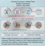
) in the enclosure wall between the penetrations (holes for connectors) of circuit conductors.

Option 2: Cutout size is not important electrically, just has to be large enough for mechanical connection of all the circuit conductors and so there is no ferromagnetic material between them.
 

GoldDigger

Moderator
Staff member
Location
Placerville, CA, USA
Occupation
Retired PV System Designer
The guide I apply when trying to figure out how many cuts and where is that if I try to draw any circle on the surface of the box that does not encircle all of the phases and the neutral (if any), that circle must always cross at least one slot.
So for a three phase three wire system with the wires spaced in a triangle, I need only two slots.

Tapatalk!
 

Smart $

Esteemed Member
Location
Ohio
The guide I apply when trying to figure out how many cuts and where is that if I try to draw any circle on the surface of the box that does not encircle all of the phases and the neutral (if any), that circle must always cross at least one slot.
So for a three phase three wire system with the wires spaced in a triangle, I need only two slots.
I believe it always ends up being one slot less than the number of circuit conductors... :D
 

augie47

Moderator
Staff member
Location
Tennessee
Occupation
State Electrical Inspector (Retired)
Here's a relevant picture that Rob posted in another thread showing some MI single conductor terminations.


MICable01.jpg
 

GoldDigger

Moderator
Staff member
Location
Placerville, CA, USA
Occupation
Retired PV System Designer
I believe it always ends up being one slot less than the number of circuit conductors... :D
True, that will be the minimum number, and if you put in more than that you run the risk of cutting out a section of the box wall.
But it would also be possible to make that number of cuts in the wrong places and still end up with a violation as well as a section of the box falling out. :happyyes:
 

rayp1

Member
Location
Phoenix, Az, USA
Aluminum Glands

Aluminum Glands

Does it matter that Aluminum glands are used for the terminated power cables installed in and out of the transformer enclosure?

A recent visit to the site revealed a comment that the inspector allowed this as acceptable because of the Al connector. The code mentions wall section to be AL. I feel this will be resurrected again as an issue to address. Slots seem to be the answer which will take a crew about two weeks to complete with 38 transformers to repair.

Thank you for any insights on this current development.
 
Status
Not open for further replies.
Top