Caleb907
Member
- Location
- Anchorage, AK, USA
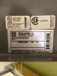
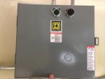
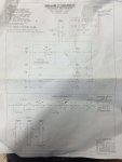
Hello, I'm currently working on a school up here in remote Alaska and I need help with how to wire this contactor correctly. All of the receptacle power in the science room is switched thru this contactor (Square D), mechanically held and a H.O.A. The e-stop is mounted next to the door so that a teacher can shutdown all of the power in case of an emergency and it's a momentary push button (NO/NC contacts). So I guess my question is if I wire my e-stop through the auto, where do I land the leg coming back, so that when they push it, it won't latch again as soon as they take their hand off the push button? I guess I don't understand what keeps the relay from changing state as the button is released? I see that there is a terminal block with one terminal labeled(1), the other(2), which is my line voltage and neutral, and according to the schematic there is an (A1) and (A2) which appear to be on the relay. It all appears to be pre wired from the factory. Although it shows a dotted line labeled "two-wire control" thru a NO contact between (A1) and (A2) which I'm guessing is my auto.... (A2) is my neutral off my relay though.... It seems no matter how I wire it, it latches and unlatches when I press the e-stop. I feel like its so simple but it's just not clear to me what the heck I need to do!! Please help, thanks, Caleb