cor2man
Member
- Location
- lincolnton NC
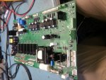
I have a 150HP AB Impact 1336 drive that has started giving me faults for DC bus precharge timeout. After looking through the boards I found a flown F3 fuse (in picture)
Drive can be powered up and all voltages on the gate drive board tests good. Everything works on drive but there is a enable inhibit because of the DC bus precharge timout.
When measured the DC bus measures the proper +-700VDC
If I monitor the DC bus from the drives interface it claims that the BUS voltage is zero.
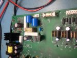
I am assuming that the fuse that blew (as drive was powered up) is connecting to a circuit that is directly being used to measure my DC bus. I cannot understand how this is working and so far have not found any issues with any components in line with this circuit. It appears to input the DC bus voltage and run it through a series of resistors and an op-amp which then switch the voltage out via a switcher.
Any information or help on this drive would be appreciated, I have attached pictures of the gate drive board and a closup of the circuit and fuse giving me problems. Any information about how a 1336 this size senses DC bus voltage would be much appreciated


Drive can be powered up and all voltages on the gate drive board tests good. Everything works on drive but there is a enable inhibit because of the DC bus precharge timout.
When measured the DC bus measures the proper +-700VDC
If I monitor the DC bus from the drives interface it claims that the BUS voltage is zero.
I am assuming that the fuse that blew (as drive was powered up) is connecting to a circuit that is directly being used to measure my DC bus. I cannot understand how this is working and so far have not found any issues with any components in line with this circuit. It appears to input the DC bus voltage and run it through a series of resistors and an op-amp which then switch the voltage out via a switcher.
Any information or help on this drive would be appreciated, I have attached pictures of the gate drive board and a closup of the circuit and fuse giving me problems. Any information about how a 1336 this size senses DC bus voltage would be much appreciated