Has anyone used a Ground Continuity Relay?

Status
Not open for further replies.

factoryrat

Member
Location
Detroit
I am looking at a GM420 Digital Ground Continuity Relay for AC Systems made by Bender.

http://www.bender-in.com/fileadmin/products/doc/GM420_DB_en.pdf

The literature says the GM420 is a Loop Monitor to monitor the PE conductor in AC systems. One of my questions is: What is the ?PE conductor?? Is that a fancy way of saying the ground wire / circuit?

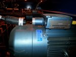
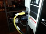
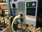
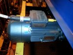
My main problem is I need to monitor whether a power cable is connected to a Motor. You see, the 480 Volt AC power feed cable has Quick Disconnects on both ends of cable and can be easily disconnected. The 4 wire, 3-phase, 480v cable is fed from a VFD and supplies a motor. The VFD does not monitor whether this cable is connected or not; but, I need to know before I release the brake on motor. Without the power cable connection I have no power on the motor (therefore no torque). VFD will release brake and load will fall.

I was wondering if I could use the GM420 relay to monitor the ground loop of the cable to determine if power cable is connected or disconnected from motor? In other words, I would use the GM420 as a "cable connection monitor" and use the relay to provide an interlock signal that would let me know and prevent me from releasing the motor brake when motor cable was disconnected. Any thoughts or comments are appreciated.
 

SceneryDriver

Senior Member
Location
NJ
Occupation
Electrical and Automation Designer
If I'm reading between the lines correctly, am I correct in that the motor brake is connected with a cable that's separate from the motor supply cable? Assuming that's the case, perhaps there's a different approach you could try. Use two conductors in the brake cable (or replace the current cable with one that has two extra conductors) to form a loop. Power comes from the drive cabinet, flows down one wire in the brake cable, through the connector at the brake, and then loops back out through another pin in the brake connector and flows back to the drive cabinet. The signal then does exactly the same thing and loops through the motor cable and connector. When the signal gets back to the drive cabinet the second time, it powers the coil of a relay.

That relay is wired to switch the RUN signal (or possibly Safe Troque Off, if you have it) to the drive. If the brake cable is disconnected, the drive won't run, preventing the load from dropping. If the motor cable is disconnected, the drive won't run, preventing the motor from attempting to drive through the brake. I'd strongly recommend using 120vac control power and a 120vac-coil relay for this, as DC wiring will tend to pick up nasty noise from traveling in the VFD power cable. The relay won't care either way, but if you use 24vdc the other devices connected to that power supply might.

I've used this approach several times, and it's worked very well. It's simple, easy to troubleshoot, and possibly cheaper than a dedicated fancy ground check relay; I'm not convinced that relay would actually work for your intended application anyway.


SceneryDriver
 

Razzap

Member
PE is Potential Earth in the rest of the world, or ground here in the USA. PE wire is usually green with yellow stripes, or is it the other way around?
 

Jraef

Moderator, OTD
Staff member
Location
San Francisco Bay Area, CA, USA
Occupation
Electrical Engineer
Is this still the same one you posted on in the other forum, where you are using the ArmorStart drive? If so, that cable lock plan didn't work out then? What happened?

The Bender relay is designed for EU systems where they do grounding (PE) systems differently from us. You would need another reference wire from your motor ground point that is DIFFERENT from the EGC, back to where the relay is, and it monitors the difference to know if the ground (PE) is discontinuous. If this is that same issue, I don't think you have a way to get that second ground wire back for reference.

This sort of system is however used here in North America a lot in underground mining, the term you can search on is "trailing cable relays", but here are the three I know of;
  • Startco (now Littlefuse) has some, very similar to the Bender but without the need for the 2nd wire. However for them to work, you need a special little "terminator" at the motor end, and that can be problematic when it comes to common mode noise due to the VFD being used. The Startco one includes a Ground Fault feature as well which you don't really need, but I don't know if it could be used without it, you'd need to ask.
  • I've also seen one used that did not have GF protection, it came from a company called Patton and Cooke, but I looked and didn't see any details on it so again you'd have to talk to them. Good people though, I did a bunch of work with them years ago on an underground mine up in Northern BC.
  • AMR (American Mining Research) is a very commonly used one and I THINK this version works on it's own. But you have to be a registered user to download info, and I don't have the inclination to do so any more. At one time I was pissed at them because MSHA was mandating one of their products, and they were the only possible source, and the company was founded by ex MSHA inspectors. A little too cozy for me. It's not to say they weren't good products, they were. I just hate not being able to chose on my own.
Hope that helps.
 
Last edited:

Aleman

Senior Member
Location
Southern Ca, USA
Just curious as to why this is an issue. Are the connectors regularly disconnected?
Another thought similar to SceneryDriver's is a loop through your cable....but use VFD cable. This will have 2 control wires shielded from the motor wires.
This is assuming you have extra pins available.
Otherwise the ground continuity relay looks like it would work.
 

factoryrat

Member
Location
Detroit
If I'm reading between the lines correctly, am I correct in that the motor brake is connected with a cable that's separate from the motor supply cable? Assuming that's the case, perhaps there's a different approach you could try. Use two conductors in the brake cable (or replace the current cable with one that has two extra conductors) to form a loop. Power comes from the drive cabinet, flows down one wire in the brake cable, through the connector at the brake, and then loops back out through another pin in the brake connector and flows back to the drive cabinet. The signal then does exactly the same thing and loops through the motor cable and connector. When the signal gets back to the drive cabinet the second time, it powers the coil of a relay.

That relay is wired to switch the RUN signal (or possibly Safe Troque Off, if you have it) to the drive. If the brake cable is disconnected, the drive won't run, preventing the load from dropping. If the motor cable is disconnected, the drive won't run, preventing the motor from attempting to drive through the brake. I'd strongly recommend using 120vac control power and a 120vac-coil relay for this, as DC wiring will tend to pick up nasty noise from traveling in the VFD power cable. The relay won't care either way, but if you use 24vdc the other devices connected to that power supply might.

I've used this approach several times, and it's worked very well. It's simple, easy to troubleshoot, and possibly cheaper than a dedicated fancy ground check relay; I'm not convinced that relay would actually work for your intended application anyway.


SceneryDriver

The power to the motor is from the VFD and is PWM. The VFD doesn't know/monitor when the Power cable from VFD to Lift Motor is disconnected. The designers of equipment did not know this unsafe condition existed; therefore, present controls do not monitor or look for this condition. This Power cable got disconnected (one time) and VFD did not know Lift Motor had no power. So when an operator tried to lower Lift the brake released, there was no torque on motor, and the load fell to the floor.

I posted this before on another forum and got some great information. I appreciate all the knowledge shared with me. I attached a couple photos (a picture is worth a .....) to clarify what I am talking about.

Thank you SceneryDriver for your thoughts and time but I do not think I can implement them in this scenario.

Pic 1: This is at VFD. Black cable is Motor Power and yellow cord is Brake Power.
Pic 2: Lift Motor power can be easily disconnected on floor level at VFD.
Pic 3: Picture of Lift Motor and motor pecker head. Motor Pwr cable and yellow brake cable connected.
Pic 4: Picture shows how the cable was disconnected when I lowered Hoist and it fell. This was the Backup Drive and it had not been used for a long time. From the HMI the Backup Drive was accidently selected (an easy to do fat finger). When I selected ?Lower Hoist? the brake released, and with no power and therefore no torque on Motor, the Lift fell to the ground. You can see the Main Drive in the background.
 

Attachments

  • pic4.jpg
    pic4.jpg
    52.6 KB · Views: 1
  • pic2.jpg
    pic2.jpg
    46.8 KB · Views: 1
  • pic1.jpg
    pic1.jpg
    78.2 KB · Views: 1
  • pic3.jpg
    pic3.jpg
    59.8 KB · Views: 1

factoryrat

Member
Location
Detroit
Is this still the same one you posted on in the other forum, where you are using the ArmorStart drive? If so, that cable lock plan didn't work out then? What happened?

The Bender relay is designed for EU systems where they do grounding (PE) systems differently from us. You would need another reference wire from your motor ground point that is DIFFERENT from the EGC, back to where the relay is, and it monitors the difference to know if the ground (PE) is discontinuous. If this is that same issue, I don't think you have a way to get that second ground wire back for reference.

This sort of system is however used here in North America a lot in underground mining, the term you can search on is "trailing cable relays", but here are the three I know of;
  • Startco (now Littlefuse) has some, very similar to the Bender but without the need for the 2nd wire. However for them to work, you need a special little "terminator" at the motor end, and that can be problematic when it comes to common mode noise due to the VFD being used. The Startco one includes a Ground Fault feature as well which you don't really need, but I don't know if it could be used without it, you'd need to ask.
  • I've also seen one used that did not have GF protection, it came from a company called Patton and Cooke, but I looked and didn't see any details on it so again you'd have to talk to them. Good people though, I did a bunch of work with them years ago on an underground mine up in Northern BC.
  • AMR (American Mining Research) is a very commonly used one and I THINK this version works on it's own. But you have to be a registered user to download info, and I don't have the inclination to do so any more. At one time I was pissed at them because MSHA was mandating one of their products, and they were the only possible source, and the company was founded by ex MSHA inspectors. A little too cozy for me. It's not to say they weren't good products, they were. I just hate not being able to chose on my own.
Hope that helps.

Yes, it is me again asking the same questions. Sorry. I guess I am looking for a miracle or something like the Rosetta Stone of VFDs - lol. But seriously ? thank you for the information you have given me. I take my job seriously and I can tell when someone is very knowledgeable on a subject and I rate you as an expert. Also thanks to those that gave the PE definitions ? I hope all this info makes me a better electrician who makes fewer mistakes in the future.
 

gar

Senior Member
Location
Ann Arbor, Michigan
Occupation
EE
141016-1107 EDT

factoryrat:

Consider this approach that will depend upon the VFD itself. Assume the VFD can be programmed for a low speed and low torque limit

Create a selectable VFD mode with speed set at minimum, and torque limit to minimum. This should be a torque that won't overload the brake. I would expect the brake has more torque locking capability than the motor has full output capability which means you could apply full torque, but better to not apply full torque.

In your control logic for raising or lowering the load always go first to a test mode that applies this minimum torque before releasing the brake, and test that the VFD sees torque. If the VFD can not provide motor torque, then use current or power measurement to the motor.

Since you used the term VFD I have to assume the motor is an AC induction or synchronous motor.

However, you need to know that the VFD is not damaged by having no motor load.

The above is probably good because it may imply that all three phases are connected to the motor.

If the above is not workable, then what does the output of the VFD look like when off (from an impedance point of view). If a small voltage can be applied you can test for continuity thru the motor.

.
 

gar

Senior Member
Location
Ann Arbor, Michigan
Occupation
EE
141016-1135 EDT

Another approach:

Mount an encoder on the motor. Upon release of the brake if the wrong motion is detected from the encoder, then reapply the brake and set an alarm.

This is not as good as knowing that the motor is connected.

Or:

At the motor put a motor voltage or current sensor connected to a relay that must be energized to enable the brake to be released. In general a brake for this application will be in the braking state with no voltage applied. Thus, the relay from the voltage or current sensor would have a normally open contact. This also means the circuitry to control this relay will have to have power or the relay won't close, and the brake won't release.

.
 

Jraef

Moderator, OTD
Staff member
Location
San Francisco Bay Area, CA, USA
Occupation
Electrical Engineer
141016-1107 EDT

factoryrat:

Consider this approach that will depend upon the VFD itself. Assume the VFD can be programmed for a low speed and low torque limit

Create a selectable VFD mode with speed set at minimum, and torque limit to minimum. This should be a torque that won't overload the brake. I would expect the brake has more torque locking capability than the motor has full output capability which means you could apply full torque, but better to not apply full torque.

In your control logic for raising or lowering the load always go first to a test mode that applies this minimum torque before releasing the brake, and test that the VFD sees torque. If the VFD can not provide motor torque, then use current or power measurement to the motor.

Since you used the term VFD I have to assume the motor is an AC induction or synchronous motor.

However, you need to know that the VFD is not damaged by having no motor load.

The above is probably good because it may imply that all three phases are connected to the motor.

If the above is not workable, then what does the output of the VFD look like when off (from an impedance point of view). If a small voltage can be applied you can test for continuity thru the motor.

.

141016-1135 EDT

Another approach:

Mount an encoder on the motor. Upon release of the brake if the wrong motion is detected from the encoder, then reapply the brake and set an alarm.

This is not as good as knowing that the motor is connected.

Or:

At the motor put a motor voltage or current sensor connected to a relay that must be energized to enable the brake to be released. In general a brake for this application will be in the braking state with no voltage applied. Thus, the relay from the voltage or current sensor would have a normally open contact. This also means the circuitry to control this relay will have to have power or the relay won't close, and the brake won't release.

.
gar,
Part of the problem here was from the selection of the VFD, being that they wanted the machine mounted version. That VFD is not a "Vector" drive, so no torque control capabilities, no capability of a "test mode" (TorqProv option in AB speak), it's strictly V/Hz.

Problem #2 is that the cable connecting the VFD to the motor is not changeable, so he has no more wires for anything back and forth. That's how he ended up with the brake being powered by a DIFFERENT cable than the one powering the motor. The glitch that happened is that the MOTOR cable came disconnected, but the cable going to the BRAKE did not, otherwise the brake would have engaged. So the solution is to know that the motor cable has come off so that they CAN kill power to the brake and let it engage. So in the other forum, a voltage relay to sense whether or not the VFD was still sending power to the motor was discussed, but there the problem is that voltage monitor relays don't like being on the output of a VFD, and when stopped the voltage is zero anyway. Hence the ground monitor to detect if the EGC is not connected because it is already there in the VFD-to-motor cable, so no ground continuity means the circuit must be broken.

But your first thought is a good one actually. Even though that drive is not capable of torque control, is IS capable of DC Injection Braking, which means current will flow to the motor. If there is a way to monitor very very low current flow while in DCIB, ie not enough to really do anything but enough to see, then there is a way to detect a disconnect of the cable if there is not at LEAST that small threshold value of current flowing (when running, there will of course be more).

factoryrat, I'm going to check on that for you, back in a while.
 

gar

Senior Member
Location
Ann Arbor, Michigan
Occupation
EE
141017-0826 EDT

Jraef:

What does the Allen-Bradley VFD do when the motor rotor is locked? Is there any signal indicating this state? How long can the VFD and motor tolerate a locked rotor condition?

If DC injection braking is applied, then how long can it be applied, what is the current level, and are all three phases energized?

Can the VFD detect that there is no current flow to a phase? In other words detect a lost phase?

Internal or external to the VFD can the current of each phase be monitored? If not, then why not?

.
 
Status
Not open for further replies.
Top