sdickson
Member
- Location
- Winnipeg, Manitoba, Canada
Our current supply transformer at work has a range of 146A-7000A, in order to preform lower current tests on CTs I need to lower the output current to around 30A.
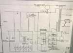
For example, the CT's resistance is around 2.46m?, to achieve 30A output I need to set the voltage of my supply transformer to around .00246*30=.0738V, which is lower than the minimum .49V output of the transformer. I've thought of a couple of ways to do this, the easiest of which would be installing a very low resistance, high current resistor on the output. One that I've spec'd out is a .209?, 200A, 8300W rated ribbon resistor. So using this resistor to try and achieve 30A output I should have .209+.00246=.21146? which would give me 30A at .21146*30=6.34V which the transformer can handle. Does this sound like it would work?
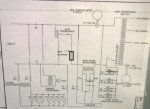
Another option I considered is installing another buck transformer in series with the one already installed and using that to bump down the transformer's output voltage. I'd rather not pursue this option as it would involve taking apart the supply and installing new hardware.
The only reason I'm not simply reducing my input voltage is because I think the relays seen at the bottom left of the schematic won't be able to operate otherwise.
Let me know what you guys think and if I'm totally off base with all this, please let me know. I've also included schematics for both of the solutions described above.
Thanks!
For example, the CT's resistance is around 2.46m?, to achieve 30A output I need to set the voltage of my supply transformer to around .00246*30=.0738V, which is lower than the minimum .49V output of the transformer. I've thought of a couple of ways to do this, the easiest of which would be installing a very low resistance, high current resistor on the output. One that I've spec'd out is a .209?, 200A, 8300W rated ribbon resistor. So using this resistor to try and achieve 30A output I should have .209+.00246=.21146? which would give me 30A at .21146*30=6.34V which the transformer can handle. Does this sound like it would work?
Another option I considered is installing another buck transformer in series with the one already installed and using that to bump down the transformer's output voltage. I'd rather not pursue this option as it would involve taking apart the supply and installing new hardware.
The only reason I'm not simply reducing my input voltage is because I think the relays seen at the bottom left of the schematic won't be able to operate otherwise.
Let me know what you guys think and if I'm totally off base with all this, please let me know. I've also included schematics for both of the solutions described above.
Thanks!