YY Transformer with lost phase on the primary side

Status
Not open for further replies.

kwired

Electron manager
Location
NE Nebraska
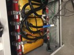
I have attached a pic of a open Y/open delta connection. I think this is happening between the 208 windings and the 3 leg common core. The other phase is being created by the 3 leg common core inducing into the 480V Y secondary. At first I thought this would not work because of the 30% phase shift from Y to delta, but when it goes back from delta to Y, I think it goes back in phase. Notice the primary side connection in the pic, with just 2 phases and the neutral. This is exactly what is there when one phase is disconnected on the grounded Y primary.
Any thoughts on this?

I am not seeing any relevance to the photo other then the primary is similar configuration to what you say you have with an open circuit in one of the input conductors. Otherwise you don't have a picture of a common core and the secondary as described in your OP is supposed to be wye connected and also on common core.:?

What you do have pictured there is a common arrangement for open delta secondary services from POCO's around here when transformer bank is made up of single phase transformers.

I think if you drew same thing with a third transformer and a wye secondary - loss of an input line would result in no voltage on the corresponding output phase, but if on a common core you may see some voltage output on the otherwise lost phase- but may not be at the correct phase angle or have any near the normal output ability.

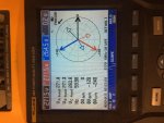
Maybe the fact your inverter did not go off line is why you have correct phase angle? Or did you test this phase angle without the inverter connected?
 
Last edited:

coop3339

Senior Member
Location
NJ
I visited the site today and tested the transformer. I found it was making 268, 268, 264 to N & 470,465,465, with one leg pulled on the 208/utility side. The phase angle was good 0, 120, 240. There was nothing connected on the 480 side during testing. C phase was also a little wavy and slightly misshapen on the traces, but not too bad. The only way I can see this happening is through the core acting as a delta connection.

The pic was meant to show how it is possible to have an open Wye connection with just 2 phases and a neutral on the primary side, with a delta secondary and make 3 phase power.

I did the same test with a Delta/wye transformer at another site and found 266, 132, 143 for the voltages.

Please let me know if anyone has any other thoughts as to why this would happen, other than the core acting as a delta connection and generating the third leg in the secondary.

Thanks
 

coop3339

Senior Member
Location
NJ
Hi Mbrooke,

I think disconnecting the ground and neutral from the utility side terminal would get rid of the problem I'm having, but I didn't try it because I wasn't sure it would not cause a problem. I think the best solution is to use a delta/Y transformer.

I have attached a pic of the phases on the power meter if any one is interested.
 

Attachments

  • IMG_8531.jpg
    IMG_8531.jpg
    146 KB · Views: 0
  • IMG_8532.jpg
    IMG_8532.jpg
    146.4 KB · Views: 0

coop3339

Senior Member
Location
NJ
No but I have a Pic of it being tested where you can see the conductor disconnected. I should have gotten one but I didn't think of it at the time. I suspect it would show a phase being made on it also.
 

Attachments

  • IMG_8534.jpg
    IMG_8534.jpg
    139.5 KB · Views: 1

winnie

Senior Member
Location
Springfield, MA, USA
Occupation
Electric motor research
I've had to mull this for a while, but I am in agreement that the common core is the link, and further the phase angle of the 'derived' phase is _supposed_ to be correct, no 'delta' needed.

The flux in the 'un driven' leg of the core is the sum of the flux in the other two legs. So the flux in leg A (from top to bottom) plus the flux in leg B (from top to bottom) will equal the flux in leg C, but _from bottom to top_. When you consider the direction of things as you account for the flux in the transformer core, you will see that the flux in the 'un driven' leg matches what it would be had it been driven.

-Jon
 

Bugman1400

Senior Member
Location
Charlotte, NC
It is still hard for me to digest that the normal voltage can be induced onto the lost leg but, that is exactly what happens for a three-leg common core xfmr w/ g-wye primary. Thanks to the OP that posted the picture of the xfmr, there is no doubt its a three-leg common core xfmr. Other type of common cores like a shell or four or five leg xfmr would not induce the normal voltage as seen in the OP's case. Also, it appears that the g-wye configuration also plays a part. So, if the ground was removed it would also not induce the normal voltage.

I forgot to attach the link to the paper that supports this......

http://www.cce.umn.edu/documents/cp...ransformersanalysisandprotectionalgorithm.pdf
 

Haji

Banned
Location
India
Haji,

Actually, its about 58%!

Regards, Phil Corso
Yes if power output from only two phases taken into account:1.732*phase voltage*line current/3*phase voltage*phase(=line) current= 58%.However, with one phase out, the transformer is still capable of 66% output by loading each phase up to 22% without overloading it!
 
Status
Not open for further replies.
Top