Weird (and Illegal !) 3-way Switch

Status
Not open for further replies.

flashlight

Senior Member
Location
NY, NY
Occupation
Electrician, semi-retired
I have heard of some strange and noncompliant schemes for wiring 3-ways, such as the "California" method.

But I had never seen or anticipated what I ran into today in an old Victorian House. Took me a while to piece together what some "electrician" had done, a long time ago:

A staircase with a light, 3-way switches top and bottom. But, no communication between top and bottom switch boxes. No travelers. Instead, the top box and the bottom box each sent one conductor to the load. Not one cable, one conductor. Then, since each box contained a hot (same circuit) and a neutral, they wired the 3-way with the wire going to the load at the common terminal, and the hot and (gasp) the neutral at the traveler terminals.

So, when the switches were in the right position, they had a hot from the top and a neutral from the bottom at the light and Voila ! it lit. Flip one or the other switch and they had either 2 hots or 2 neutrals at the load, so no light. Flip one or the other switch and Voila ! light again. The weird thing about this setup (ok there's lot's of weird things) is that it changed polarity at the load depending on the switch positions. Bizarre and illegal to be sure, but it worked just like a 3-way switch for 50 years.

Has anyone else ever seen this scheme ?
 

sparkyrick

Senior Member
Location
Appleton, Wi
I have heard of some strange and noncompliant schemes for wiring 3-ways, such as the "California" method.

But I had never seen or anticipated what I ran into today in an old Victorian House. Took me a while to piece together what some "electrician" had done, a long time ago:

A staircase with a light, 3-way switches top and bottom. But, no communication between top and bottom switch boxes. No travelers. Instead, the top box and the bottom box each sent one conductor to the load. Not one cable, one conductor. Then, since each box contained a hot (same circuit) and a neutral, they wired the 3-way with the wire going to the load at the common terminal, and the hot and (gasp) the neutral at the traveler terminals.

So, when the switches were in the right position, they had a hot from the top and a neutral from the bottom at the light and Voila ! it lit. Flip one or the other switch and they had either 2 hots or 2 neutrals at the load, so no light. Flip one or the other switch and Voila ! light again. The weird thing about this setup (ok there's lot's of weird things) is that it changed polarity at the load depending on the switch positions. Bizarre and illegal to be sure, but it worked just like a 3-way switch for 50 years.

Has anyone else ever seen this scheme ?
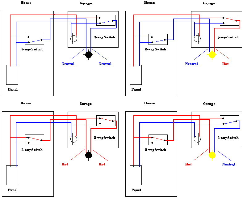
I gotta make a line diagram for that one, LOL!
 

al hildenbrand

Senior Member
Location
Minnesota
Occupation
Electrical Contractor, Electrical Consultant, Electrical Engineer
The weird thing about this setup (ok there's lot's of weird things) is that it changed polarity at the load depending on the switch positions. Bizarre and illegal to be sure, but it worked just like a 3-way switch for 50 years.

Has anyone else ever seen this scheme ?
You described it, and its operation perfectly. In the early days of K&T this threeway scheme was Code compliant. Hard to believe, today, but it was absolutely legal at one time.

Now, here's an even more interesting little side effect of it. Some threeway switches will, while being switched, briefly connect the two traveler terminals on the switch together. Naturally, this blows the overcurrent protection, by shorting the Hot to the Neutral.

Another side effect shows up on a service upgrade or a panel change-out. The upstairs and the downstairs sources for the Hot and Neutral connected at each switch had a good chance of being on different circuits. To not put 240 Volts on the lamp, the two circuits have to come off of the same panel bus. The one switch position of Hot to Hot, that should result in the lamp being off, will blow it out, every time.
 

480sparky

Senior Member
Location
Iowegia
Commonly used to power up detached garages, and the addition of one more conductor allowed the use of a pair of 3-ways between the house and garage.

Calif3wayanim.gif
 

GoldDigger

Moderator
Staff member
Location
Placerville, CA, USA
Occupation
Retired PV System Designer
Commonly used to power up detached garages, and the addition of one more conductor allowed the use of a pair of 3-ways between the house and garage.

I see at least three potential issues with current code:
1. If the hots come from different circuits/different panels.
2. If the lampholder is screw shell, reverse polarity is not allowed.
3. Color of wires to lamp, since each is sometimes hot, sometimes neutral.
 

kwired

Electron manager
Location
NE Nebraska
I have heard of some strange and noncompliant schemes for wiring 3-ways, such as the "California" method.

But I had never seen or anticipated what I ran into today in an old Victorian House. Took me a while to piece together what some "electrician" had done, a long time ago:

A staircase with a light, 3-way switches top and bottom. But, no communication between top and bottom switch boxes. No travelers. Instead, the top box and the bottom box each sent one conductor to the load. Not one cable, one conductor. Then, since each box contained a hot (same circuit) and a neutral, they wired the 3-way with the wire going to the load at the common terminal, and the hot and (gasp) the neutral at the traveler terminals.

So, when the switches were in the right position, they had a hot from the top and a neutral from the bottom at the light and Voila ! it lit. Flip one or the other switch and they had either 2 hots or 2 neutrals at the load, so no light. Flip one or the other switch and Voila ! light again. The weird thing about this setup (ok there's lot's of weird things) is that it changed polarity at the load depending on the switch positions. Bizarre and illegal to be sure, but it worked just like a 3-way switch for 50 years.

Has anyone else ever seen this scheme ?
So what is it that you call a California three way? What you described is what I have heard called a California three way, a Chicago three way, or a Carter three way, and possibly some other names but those three seem to be most common.
 

ActionDave

Chief Moderator
Staff member
Location
Durango, CO, 10 h 20 min from the winged horses.
Occupation
Licensed Electrician
So what is it that you call a California three way? What you described is what I have heard called a California three way, a Chicago three way, or a Carter three way, and possibly some other names but those three seem to be most common.
Similar, but a California three way uses two wire for travelers and keeps the polarity at the light proper.
 

flashlight

Senior Member
Location
NY, NY
Occupation
Electrician, semi-retired
Well, you learn something new every day. I've taken apart a lot of old wiring, but I guess I kind of missed the K&T era--

Nice illustration, 480Sparky !
 

kwired

Electron manager
Location
NE Nebraska
Well, you learn something new every day. I've taken apart a lot of old wiring, but I guess I kind of missed the K&T era--

Nice illustration, 480Sparky !
I think most of us missed it as you would need to be 85 -90 years old just to have been less then 10 years old when this method was phasing out, but there are a lot of existing installations still out there.
 

GerryB

Senior Member
I have heard of some strange and noncompliant schemes for wiring 3-ways, such as the "California" method.

But I had never seen or anticipated what I ran into today in an old Victorian House. Took me a while to piece together what some "electrician" had done, a long time ago:

A staircase with a light, 3-way switches top and bottom. But, no communication between top and bottom switch boxes. No travelers. Instead, the top box and the bottom box each sent one conductor to the load. Not one cable, one conductor. Then, since each box contained a hot (same circuit) and a neutral, they wired the 3-way with the wire going to the load at the common terminal, and the hot and (gasp) the neutral at the traveler terminals.

So, when the switches were in the right position, they had a hot from the top and a neutral from the bottom at the light and Voila ! it lit. Flip one or the other switch and they had either 2 hots or 2 neutrals at the load, so no light. Flip one or the other switch and Voila ! light again. The weird thing about this setup (ok there's lot's of weird things) is that it changed polarity at the load depending on the switch positions. Bizarre and illegal to be sure, but it worked just like a 3-way switch for 50 years.

Has anyone else ever seen this scheme ?
Thanks, can't wait to draw it out. I have run into 3-ways with knob and tube and had no idea how they worked.
 

al hildenbrand

Senior Member
Location
Minnesota
Occupation
Electrical Contractor, Electrical Consultant, Electrical Engineer
So what is it that you call a California three way?

a California three way uses two wire for travelers and keeps the polarity at the light proper.

Where do you find "two wire" K@ T:cool: Must have been a NM cable method more so then a K@T method.

Here's the most basic configuration of the California threeway, what I like to refer to as the Traveling Bus threeway (with thanks to Benny. R.I.P.) NOTE: this is NOT what the OP is describing.

TwoWireTravellingBus3Way.jpg


The circuit feature that distinguishes a California threeway (Traveling Bus) from others is that the conductor that connects threeway switch Common to threeway switch Common does nothing else, and no other connection are made anywhere along, or at the ends of, the Common to Common conductor.

Here's another example of the California (Traveling Bus):

TravellingBusHalfSwitchedReceptacle.jpg
 

kwired

Electron manager
Location
NE Nebraska
Here's the most basic configuration of the California threeway, what I like to refer to as the Traveling Bus threeway (with thanks to Benny. R.I.P.) NOTE: this is NOT what the OP is describing.

TwoWireTravellingBus3Way.jpg


The circuit feature that distinguishes a California threeway (Traveling Bus) from others is that the conductor that connects threeway switch Common to threeway switch Common does nothing else, and no other connection are made anywhere along, or at the ends of, the Common to Common conductor.

Here's another example of the California (Traveling Bus):

TravellingBusHalfSwitchedReceptacle.jpg
I guess I have seen that drawing a few times - particularly on this forum, but I can't ever recall running into that at an installation.

Would not be an illegal install if in a raceway and all conductors were in the same raceway if the light were between the two switches in the run. Would use 1 more conductor then conventional methods to the end three way if there was no more loads beyond the end three way.
 

al hildenbrand

Senior Member
Location
Minnesota
Occupation
Electrical Contractor, Electrical Consultant, Electrical Engineer
Would not be an illegal install if in a raceway and all conductors were in the same raceway if the light were between the two switches in the run. Would use 1 more conductor then conventional methods to the end three way if there was no more loads beyond the end three way.

The Traveling Bus (California threeway), in one switch position, parallels the hot conductor that is along one traveler with the Common to Common conductor. As the circuit conductors are normally #14 and #12, this is a violation of the small size restriction for paralleling conductors. That's a technicality, I know, and for a long time, was simply ignored by everybody.

I find the Traveling Bus (California threeway) in a lot of Fifties thru Seventies dwellings, where they are installed down long hallways with more than one light, and between house and detached garage where the threeways simultaneously control a light at the house back door and the garage service door (or driveway).

Note in the PostIt note that I drew, the neutral and hot travel different routes and require a nonmetallic wiring method. I have found this twice, in the wild, in my career, both in early Sixties living rooms.
 

don_resqcapt19

Moderator
Staff member
Location
Illinois
Occupation
retired electrician
When I was an apprentice we upgraded an old 30 amp 120 volt service to a 100 amp 120/240 volt service. There was a set of 3-ways wired with a hot and neutral connected to the traveler terminals at each switch ...the only problem was that the two switches were on opposite hot legs.
 

kwired

Electron manager
Location
NE Nebraska
The Traveling Bus (California threeway), in one switch position, parallels the hot conductor that is along one traveler with the Common to Common conductor. As the circuit conductors are normally #14 and #12, this is a violation of the small size restriction for paralleling conductors. That's a technicality, I know, and for a long time, was simply ignored by everybody.

I find the Traveling Bus (California threeway) in a lot of Fifties thru Seventies dwellings, where they are installed down long hallways with more than one light, and between house and detached garage where the threeways simultaneously control a light at the house back door and the garage service door (or driveway).

Note in the PostIt note that I drew, the neutral and hot travel different routes and require a nonmetallic wiring method. I have found this twice, in the wild, in my career, both in early Sixties living rooms.
Your calling that a technicality is correct, and that has been debated with no real consensus for certain situations like this one as to whether or not the intent for prohibiting small parallel conductors is limited to paralleling them for the purpose of making an effective larger current carrying ability conductor or if it is allowed for certain control schemes - which this "parallel" is for control scheme more so then for current carrying ability. I will let it be at no general consensus and not reopen the debate - some areas it may be deemed unacceptable others it may not.
 

al hildenbrand

Senior Member
Location
Minnesota
Occupation
Electrical Contractor, Electrical Consultant, Electrical Engineer
:D
When I was an apprentice we upgraded an old 30 amp 120 volt service to a 100 amp 120/240 volt service. There was a set of 3-ways wired with a hot and neutral connected to the traveler terminals at each switch ...the only problem was that the two switches were on opposite hot legs.

Isn't that it. :cool: I well remember my old Master working along side me as I'm apprenticing and we're doing a service upgrade on exactly the same type of service (30 Amp 120 Volt) in a two story Victorian, and he's cautioning me about landing the circuits in the new 120/240 Volt panel. . . I was in Engine School, at the time, and the insight coming from his telling me about his learning this lesson about Chicago threeways is still fresh in my mind. (Thank you, Paul Denny!)
 
Last edited:
Status
Not open for further replies.
Top