Wow, did these guys get off on a tangent. Sometimes they are too smart here. I don't know if you ever grasped the answer to your question. The intent was to give you enough variables to solve the problem. If I just tell you I have a 9.6KW resistive heater strip you can't figure out anything. Once I say it is 9.6 KWat 230 volts, you can start doing math.
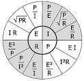
What you ultimately need is to find power at 240 volts Ohm's law tells us that P=I*E We have E, we are solving for P so we need the current. In order to get the current at 240 volts Ohm's law tells us with need the resistance, as in, I=E/R. A heat strip is a constant resistance, so no matter what the voltage, power etc. the resistance stays the same. We have wattage and voltage so E2/P=R (230*230/9600=5.51 ohms). Now using the constant resistance we get (E2/R=P) 240*240/5.51=10454 watts. There are a ton of different ways you can get to the answer, using variations of Ohm's laws. I usually go a longer way around. I find the amperage at 230 volts (I=P/E) then I find the resistance (R=E/I) Then I use that resistance to find the amperage at 240 volts then I use voltage and amperage at 240 to find the final wattage.
That is the point of the question. It is something I try very hard to walk my guys through. A very practical application for this is understanding what happens when a neutral opens or has a high resistance to ground. If you work it through you will find that when you open the neutral with a 100 watt light bulb on A and a 50 watt light bulb on B the 100 watt light bulb will get very dim and the 50 watt light bulb will burn very bright. Physically of course, the 50 watt will burn out quickly and the circuit will open, but that is another story.
") So I guess I must ask... how is nominal defined for motors vs heaters from a code perspective.
So I guess I must ask... how is nominal defined for motors vs heaters from a code perspective.