terminal block question

Status
Not open for further replies.

Designer69

Senior Member
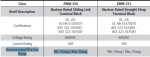
I have the following issue. I have a terminal box with the attached terminal blocks. Seems they allow max size #10 conductors but I need to disconnect the existing #12 cables on it and connect #6 cables due to extended routing.

1st question- is it ok to exceed the max recommended size shown by the vendor?
2nd question- if not, what is typically the most common way of solving this. installing new bigger term block next to it?

thank you
 

Attachments

  • term blocks.png
    term blocks.png
    23.3 KB · Views: 0

Smart $

Esteemed Member
Location
Ohio
Splice smaller conductor to larger and then terminate.
That is assuming the ampere rating is not exceeded.

If this is being done on an NRC-licensed site, check with engineering if splicing is permitted, and if so the approved means and methods.
 

Designer69

Senior Member
Splice smaller conductor to larger and then terminate.

you mean like a Raychem field splice? I am pretty leery on doing that as Smart$ said.

so I guess I'm still curious if it is a big no no to terminate #6 when it says conductor size: 10AWG max. (although vendor says recommended range)
 

Smart $

Esteemed Member
Location
Ohio
you mean like a Raychem field splice? I am pretty leery on doing that as Smart$ said.

so I guess I'm still curious if it is a big no no to terminate #6 when it says conductor size: 10AWG max. (although vendor says recommended range)
If the part specification says 10AWG MAX, you cannot use a larger conductor. If the vendor is saying (by word of mouth) it is only a recommended range, then require the vendor to furnish documentation which plainly states you can use 6AWG and make sure it includes the UL (or other NRTL) file number.
 

Designer69

Senior Member
If the part specification says 10AWG MAX, you cannot use a larger conductor.

ok that's pretty clear now, thanks. So any recommendations on the best way to do this without using a field splice? New term block w/ larger ratings next to existing term block?
 

Smart $

Esteemed Member
Location
Ohio
ok that's pretty clear now, thanks. So any recommendations on the best way to do this without using a field splice? New term block w/ larger ratings next to existing term block?
That amounts to a splice... but better than a "field" splice.

Can you replace the existing or referenced block with a one having a higher (and wider) wire range?

Another alternative may be to use pin terminals. Essentially they are compression (crimp-on) connectors with a pin that is smaller than the wire size. There are also some reducing terminals which have a wire instead of a pin. They are expensive. Both of these are basically just another splice method... so once again, check with engineering if this is permitted.
 

jumper

Senior Member
Ooops. I was on a phone earlier and did not see the NRC designation.

Yeah, a field splice is probably out. If the NRC is anything like the DoD, nothing less than act of God is likely to get one approved.
 

Jraef

Moderator, OTD
Staff member
Location
San Francisco Bay Area, CA, USA
Occupation
Electrical Engineer
As the others have said, the NRC approval is a game changer, IF that's what you are using these for. You didn't really provide enough information.

Those terminals are rated for 50A, and the terminals themselves are actually studs, the wire size is listed as "Recommended", most likely because that is based on standard ring tongue terminal dimensions for #10 wire. I think they are using 10-32 threads on the studs, so in theory if you could find an officially approved ring or fork terminal that would go onto #6 wire and fit a #10 stud that is no wider than the distance between barriers on the terminal strip, I don't see the problem if you are using it at 50A or less.

FINDING that terminal however is likely a non-starter.
 

Smart $

Esteemed Member
Location
Ohio
As the others have said, the NRC approval is a game changer, IF that's what you are using these for. You didn't really provide enough information.

Those terminals are rated for 50A, and the terminals themselves are actually studs, the wire size is listed as "Recommended", most likely because that is based on standard ring tongue terminal dimensions for #10 wire. I think they are using 10-32 threads on the studs, so in theory if you could find an officially approved ring or fork terminal that would go onto #6 wire and fit a #10 stud that is no wider than the distance between barriers on the terminal strip, I don't see the problem if you are using it at 50A or less.

FINDING that terminal however is likely a non-starter.
You are correct about stud terminals.

http://www.statesproducts.com/common/documents/Terminal Blocks_DS_en_V06.pdf

Crimp-on ring terminals for 6AWG w/#10 stud-hole are not that hard to find. If required to be traceable (i.e. nuclear-documented)... that's another matter. :D
 

Jraef

Moderator, OTD
Staff member
Location
San Francisco Bay Area, CA, USA
Occupation
Electrical Engineer
You are correct about stud terminals.

http://www.statesproducts.com/common/documents/Terminal Blocks_DS_en_V06.pdf

Crimp-on ring terminals for 6AWG w/#10 stud-hole are not that hard to find. If required to be traceable (i.e. nuclear-documented)... that's another matter. :D

I was thinking that the OUTSIDE of the ring tongue must still fit between the barriers, and that for a #6 RT, that would be wider. But I didn't look any up until now (on the phone with a boring conference call, killing time on mute so they can't here my keyboard...). I looked at Panduit.

The data and dimension sheets on those terminals unfortunately don't provide that distance directly as far as I could tell. But if you look at dimension C for a single point terminal block, the distance to the OUTSIDE of the barriers is .55" and if you look at a 2 point block, it's 1.17. So .55 = 1X + 2Y and 1.17 = 2X + 3Y where X = the space between barriers and Y = the thickness of the barriers (assuming they are all the same).

Solving for for X.
1.17 - .55 = .62 so 1X + 3Y = .62 and .62 - .55 = .07, which is what's left after removing 2Y, ergo Y = .07, so X = .41"

A Panduit P6-10R crimp lug is .47" wide, so it won't fit. He MIGHT be able to find one though, I only looked at one.
 

Smart $

Esteemed Member
Location
Ohio
I was thinking that the OUTSIDE of the ring tongue must still fit between the barriers, and that for a #6 RT, that would be wider. But I didn't look any up until now (on the phone with a boring conference call, killing time on mute so they can't here my keyboard...). I looked at Panduit.

The data and dimension sheets on those terminals unfortunately don't provide that distance directly as far as I could tell. But if you look at dimension C for a single point terminal block, the distance to the OUTSIDE of the barriers is .55" and if you look at a 2 point block, it's 1.17. So .55 = 1X + 2Y and 1.17 = 2X + 3Y where X = the space between barriers and Y = the thickness of the barriers (assuming they are all the same).

Solving for for X.
1.17 - .55 = .62 so 1X + 3Y = .62 and .62 - .55 = .07, which is what's left after removing 2Y, ergo Y = .07, so X = .41"

A Panduit P6-10R crimp lug is .47" wide, so it won't fit. He MIGHT be able to find one though, I only looked at one.
I looked at T&B RE6-10 and it has a 0.49 in. width.

I have to put your equations into question. From what I see, a 1-pole block has no barrier, and multi-pole blocks have one barrier less than number of poles (i.e. there is no end barrier)... while your equations assume one barrier greater than number of poles. That said, there's not enough evidence to say the opening width is any less than 0.55 in.
 

Smart $

Esteemed Member
Location
Ohio
What is being proposed is not a splice but a connection.
You can call it whatever you want, but it amounts to two more terminations than required. If you ever design for an NRC site, you will learn very quickly that any issue which reduces reliability is undesirable... and it doesn't matter if it seems like some trivial aspect of the overall process.
 
Status
Not open for further replies.
Top