peterrudart
Member
- Location
- san diego
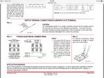
I need to wire the Potter flow switch and the 120v bell on my building. I have a dedicated and locked circuit feeding the flow switch, however the wire diagram show my hot leg landing on the common and my neutral going through the bell then landing on the N.O.. my bell is 120v and has 2 white tails and 2 balck tails. if i use the white tails as a in and out then where do i get my hot leg from for the bell?