Wattage of two 120 V ckts not equal to the wattage of a 2 pole 208 V w same current?

Status
Not open for further replies.
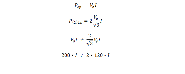
Is the wattage of two 120 V circuits the same as one 2 pole circuit with the same current? When I tried to work the math, it shows that the wattage of the 2 pole circuit does not equal the wattage of the two single pole circuits (see pic). You would think that if both single pole circuits had the same amperage as the 2 pole circuit, the power should be the same in the 2 pole circuit as in the two single pole circuits. Did I make a mistake with my math or are these two circuits not equivalent?
xrd7Y9Jl69nvps8giVOEBW90pTauH8AhTFQeRKC4Qf3aGYejmQFSSktTEqs-5M3C833UZYYbv6OpruqnkGrvFBUSikNdQ7Z5a6-8rXhni8KiPOCVj1rRTbS4OkqgHGR8bv3fth3v
 

Dennis Alwon

Moderator
Staff member
Location
Chapel Hill, NC
Occupation
Retired Electrical Contractor
I think the problem is that you are using 208V when your connected loads are 120V. If you had a 240V system it would work out
 

kwired

Electron manager
Location
NE Nebraska
Wattage is still the same, but it is misleading with a 208 Y system because of the 120 degree phase angle vs the 180 degree phase angle of a true single phase system.

If you had two 10 amp 120 volt loads (1200 watts), with the 180 degree phase angle you would see 10 amps on A, 10 amps on B, and a net of zero on the neutral. This also gives you 10 amps and 2400 watts as viewed from the A-B perspective. Open that neutral and things remain pretty much the same as far as voltage and current across each individual load.

Now put same two loads on two lines and neutral of a 208/120 Y system and you still have 10 amps on A, 10 amps on B for 2400 total watts at 120 volts, but you also have current in the neutral that is also near 10 amps. Open that neutral and the volts across each load reduces to 104 and current also goes down.
 

Ingenieur

Senior Member
Location
Earth
For the 208 you are assuming they are equal in time/phase, they are not
only in magnitude
it's not 2 x 208/(sqrt 3)
Van - Vbn
= 120/0 deg - (120/120 deg)
120(1 + oj) - (120(-0.5 + 0.866j))
120(1.5 - 0.866j)
208/-30 deg
 

gar

Senior Member
Location
Ann Arbor, Michigan
Occupation
EE
160612-1914 EDT

Becca R:

Just applying some equation to some unclear statement of a problem will not necessarily produce a correct answer to whatever is the correct question.

A resistor of 100 ohms with 120 V applied across the resistor will have a current of 1.2 A flowing thru the resistor. The power dissipated in the resistor is 1.2*1.2*100 =144 W. The current in each wire of the source is 1.2 A assuming no other loads on the source.

Connect two 100 ohm resistors in series and apply 208 V to the series combination and the current is 1.04 A thru the series combination. Whether the source is a wye, some 10 phase thing, or anything else makes no difference. Each source wire reads 1.04 A if there is no other load on the source. You figure the the total power in the series combination.

Connect that same series combination to a 208/120 wye source with the mid-point of the two resistors connected to the neutral. Now the power dissipation is 144 W in each resistor, and the current thru each resistor is 1.2 A.

With this series combination as the only load on the wye source you calculate the neutral current. It is a phasor sum. It is quite obvious that the hot line currents are 1.2 A.

See if you can present a clear statement of the question you were trying to ask.

.
 
Last edited by a moderator:

Smart $

Esteemed Member
Location
Ohio
Everyone so far is essentially saying the same thing in a different way. So I may as well stick my two cents in here for yet another.

You have three loads: 2 @ 120V 10A and 1 @ 208V 10A. They all have the same current, but the one is line-line connected for 208V.

What is the kVA of the loads? 2 @ 1.2kVA and 1 @ 2.08kVA respectively. Note the last is not the sum of the other two even though the load is contributing 10A on the each line to which the other two are connected. Why? The 10A of the line-line load current is out of phase with the line-neutral voltage.

Let us now enter the concept power factor (pf) into the picture and go with what Ingenieur presented in that the line-line voltage is 30° out of phase with the respective line-neutral voltage. If the power factor of the line-line load is 1, the power calculates to PREAL=E×I×pf=208×10×1=2.08kW. Note the kVA and kW values are the same.

So now let's examine how that is different when it gets to the source end. The 10A of line-line load current passes through two 120V line-neutral windings to complete the circuit pathway. The kVA is PAPPARENT=E×I=120×10=1.2kVA. With the load current passing through two windings: 2.4kVA.

Now enters a different power factor. Each winding sees the current as out of phase with its developed voltage... 30° out of phase, in fact. Power factor is the cosine of the voltage-to-current phase difference, the angle phi: ϕ. So it appears to the winding that the load current has a power factor of cos 30°=0.866. When we look at real power through each winding... PREAL=E×I×pf=120×10×.866=1.04kW. And since the current passes through two windings: 2.08kW, the real power consumption of the 208V load.
 

gar

Senior Member
Location
Ann Arbor, Michigan
Occupation
EE
160613-1123 EDT

Becca R:

Consider your title sentence only.
Wattage of two 120 V ckts not equal to the wattage of a 2 pole 208 V w same current?
Without defining the load all sorts of possibilities exist. Thus, assume a resistive load(s).

The total power dissipated by the two loads for the two 120 V circuits is W120 = 2*I*120 or I*240.

The total power dissipated in the 208 resistive load is W208 = I*208 or 86.7% of the power in the two 120 circuits.

If the same total series resistance of the 120 circuits was supplied with 208 V, then the 208 power would be 75% of the total 120 V circuits power.

.
 

gar

Senior Member
Location
Ann Arbor, Michigan
Occupation
EE
160613-2251 EDT

Dennis:

Just plugging numbers into a formula may produce a result, but that result can be wrong if you do not understand the derivation of the formula and how it models the problem you are trying to solve.

10 A at 208 V across a resistive load does not equal the power of 2 * 10 * 120, and never will.

.
 

GoldDigger

Moderator
Staff member
Location
Placerville, CA, USA
Occupation
Retired PV System Designer
IS this like a 120/208 volt 3 phase MWBC using only to hots and what would happen if the neutral opened?
Yes. With the neutral present you have two identical 120V loads operating at full power.
When the neutral opens you have one 240V load at twice the rated power which is seeing only 208V. The power is reduced by a factor of (208/240)**2.
 

GoldDigger

Moderator
Staff member
Location
Placerville, CA, USA
Occupation
Retired PV System Designer
Is that supposed to be a "squared" indication? As in (208/240)².

Yup. That is the way math and computer folks without superscripts often write it. "^2" is another way.
Although the full Forum editor does superscripts just fine I have not figured out a way to do it from Tapatalk.
 

Smart $

Esteemed Member
Location
Ohio
Yup. That is the way math and computer folks without superscripts often write it. "^2" is another way.
Although the full Forum editor does superscripts just fine I have not figured out a way to do it from Tapatalk.
I've not seen it that way before (or at least don't recall it)... so "often" seems to be relative. Aware of the "^2" way, as it is used in Excel and other spreadsheet programs. Can't help with doing superscripts on Tapatalk.
 

gar

Senior Member
Location
Ann Arbor, Michigan
Occupation
EE
160616-2212 EDT

The original post question was comparing the power of two loads where the line currents were equal, but different source voltages.

One circuit was a 208 V single phase source with 10 A load current. I don't think Becca R looked at the 208 V as being simply a single 2 terminal voltage source, thus single phase. True, the 208 V came from a three phase source, but that does not make the 208 V a three phase source when only two wires are used.

The other circuit in the comparison was two mostly separate 120 V single phase circuits derived from a 3 phase 208 wye. Again hot line currents were 10 A.

Obviously different resistance loads in the two different circuits. The associated resistance were selected to get the desired current at the stated voltages. The 120 V resistances were each 12 ohms, and the 208 resistance was 20.8 ohms. Note, 2*12 does not equal 20.8 ohms.

Thus, the problem is not the equivalent of a lost neutral in the 120 V circuit.

.
 

GoldDigger

Moderator
Staff member
Location
Placerville, CA, USA
Occupation
Retired PV System Designer
160616-2212 EDT

The original post question was comparing the power of two loads where the line currents were equal, but different source voltages.

One circuit was a 208 V single phase source with 10 A load current. I don't think Becca R looked at the 208 V as being simply a single 2 terminal voltage source, thus single phase. True, the 208 V came from a three phase source, but that does not make the 208 V a three phase source when only two wires are used.

The other circuit in the comparison was two mostly separate 120 V single phase circuits derived from a 3 phase 208 wye. Again hot line currents were 10 A.

Obviously different resistance loads in the two different circuits. The associated resistance were selected to get the desired current at the stated voltages. The 120 V resistances were each 12 ohms, and the 208 resistance was 20.8 ohms. Note, 2*12 does not equal 20.8 ohms.

Thus, the problem is not the equivalent of a lost neutral in the 120 V circuit.

.

The question of why two equal current loads have different power consumption for the two configurations is very closely related to the question of why two equal resistance loads give a different power in one configuration than in another.
The second discussion illuminates the first even if it does not apply directly to the numbers in the original problem.
The question of why the three phase power formula does not help comes down to the difference between load (line to line) current and lead (single wire) current and, as you noted, that the relationship between the two for balanced three phase does not hold when you have only a single phase load.
 

gar

Senior Member
Location
Ann Arbor, Michigan
Occupation
EE
160617-0937 EDT

Becca R has indicated that he understands the problem better now, but he has not indicated where his thought process was wrong.

The equation p(t) = v(t) * i(t), where p, v, and i are instantaneous values, is valid for any time and waveform. Note that this is a two terminal equation. P = V * I where P, V, and I are RMS values is valid under some conditions. An understanding of those conditions is important. RMS is a special type of averaged value.

The use of RMS generally means you need to be studying a stationary random process. An application with constant steady-state sine wave values averaged over a reasonable number of cycles can be considered a stationary random process. A stationary random process is one where the statistical values are constant from one sample period to another. So average, RMS, standard deviation, and etc. are all constant from one sample period to another in a stationary process.

I believe that Becca thought that resistive loading two hot lines of a three phase wye source to the same current magnitude would produce the same power load. Actually with his equations he proved this was not so for the load circuits he had selected.

.
 

gar

Senior Member
Location
Ann Arbor, Michigan
Occupation
EE
160617-113 EDT

Becca R:

Instead of a 12 ohm resistor load on the 120 V circuit what load can you use there to achieve the goal of a 10 A line current and 1/2 the power dissipation of the resistor across the 208 V source?

.
 
Status
Not open for further replies.
Top