Where do you see conduit tags?
You gave us a "part of the picture", not the "whole picture". Interpretation: part of the electrical plans without symbol legend and notes involved. Without those all I see is a revision cloud labeled "triangle 2". Note there is another much smaller one to the right. Without the former drawing and any pertinent notes, I have no idea what got changed (revised).
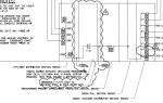
All I see with what I assume you mean conduit tags are a couple leaders with 1200 and 3000 in an oval callout symbol... and the 1200 callout is subnoted 25. To me these are feeder (wire or bus) ampacity values. Nothing about 'em says conduit. No matter what, if these are truly physically separated switchgear sections, to run conduit between them is ludicrous. Worst cases scenario, wireway. For all I know from here, it can be bus duct.