0-10V Switch Wiring

Status
Not open for further replies.

mstrlucky74

Senior Member
Location
NJ
I know I've asked this before but I can't quite get the wiring scenario.

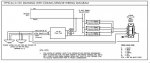
1. There is no 120v voltage from switch to ballast/driver?
2. The 120v looks like it spiced between the driver and power pack
3. If there were no sensors where would you bring your 120v circuit...to switch or in clg.?

I only ask these questions because I've been told different things about 120v wiring is needed along with the 0-10v wiring from switch to driver/light/clg box.

THanks.
 

Attachments

  • Capture.jpg
    Capture.jpg
    27.2 KB · Views: 2

hbiss

EC, Westchester, New York NEC: 2014
Location
Hawthorne, New York NEC: 2014
Occupation
EC
I see what you are talking about. This is completely unlike any of the others I have seen. The 0-10v wiring is there but the dimmer does not connect to the line, instead to goes to one side of the (parallel) ballast/drivers. I have no idea what voltage is on those conductors. If it's LV then you can use a 4/C CL2 cable. If not you treat it as we talked about before with line and LV on the same cable.

Does the manufacturer's literature give any direction here?

-Hal
 

n1ist

Senior Member
Location
Massachusetts
Occupation
Principal Electrical Engineer
The power pack contains a relay between the two reds; this provides AC power to the drivers. This relay is controlled by the blue wire on the left of the power pack (the left side is low voltage; check the manufacturer's specs to see if it is class 1 or class 2). The switch is all low voltage. It has two outputs - the 0-10v on purple and grey dim the drivers. The red and blue are a dry contact that controls the relay in the power pack to cut power to the drivers when switched off. The sensors, if used, are in parallel with that contact and can also operate the relay.

The odd thing I see is that the switch is connected between red and blue; I would think black and blue would make more sense since most sensors power packs require a connection between blue and black to turn the relay on.
/mike
 
Last edited:

mstrlucky74

Senior Member
Location
NJ
Yeas someone was telling me I need to run power and LV from the switch but I don't think so. But then I said to myself where does the 120v lighting circuit come from. Guess just branch run up in ceiling.
 

brantmacga

Señor Member
Location
Georgia
Occupation
Former Child
Yeas someone was telling me I need to run power and LV from the switch but I don't think so. But then I said to myself where does the 120v lighting circuit come from. Guess just branch run up in ceiling.

Yes, that is right, just 120v in the ceiling straight to the power pack and drivers.

Those are 24v switches. They do make 120v switches with 0-10v dimming.

I’ve done several projects that use occ sensors but also 120v switches, and they always have it drawn where the PP relay sends 120v to the switch; so the sensors always have power, but the switches do not unless the occ sensor is activated.


Sent from my iPhone using Tapatalk
 
Status
Not open for further replies.
Top