1, 2, and 3 phase Load Calculations - Need Help!

Status
Not open for further replies.

Rorshac

Member
My question involves an apparent violation of the laws of physics when summing single-pole, 3 wire, loads with other single-pole, 2 wire loads and 3-phase loads. Here is my example, maybe someone can explain the apparent disrepency.

Sample Loads on 3-phase, 208/120VAC, Panel ABC
1. One 2080VA @ 208V, single-phase, 3 wire load
2. One 1200VA @ 120V, single-phase, 2 wire load
3. One 3600VA @ 208V, three-phase, 3 wire load

TOTAL Load: 2080+1200+3600 = 6880VA

Ampere Method
Panel A B C
1. 10 10 -
2. - - 10
3. 10 10 10

TOTAL 20 20 20 = (3)(120)(20) = 7200VA

How can there be two different values for the total load on Panel ABC for the same list of equipment?

I hope I explained my point and at least made some of you think =) Let me know what you think?

-Ed
 
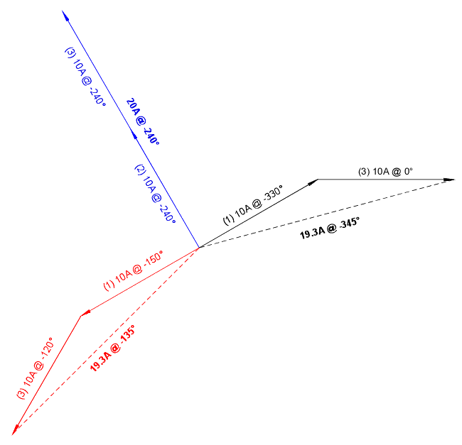
There aren't two different values. The amperages do not add up arithmetically... rather they add up algebraically (or geometrically using vectorial representations)...

calculations.gif

[Note: Angular rotation is negative in the above image]​

So you will have 19.3A on both lines A and B, and 20A on line C. You also introduced a phase shift between applied voltage and current on line A and B, hence a power factor...

Line A: 19.3A x 120V x cos 15? = 2237VA
Line B: 19.3A x 120V x cos 15? = 2237VA
Line C: 20A x 120V = 2400VA

Total VA = 6874, discrepancy attributed to rounding​
 
hardworkingstiff said:
How did you determine the angles to use on the diagram?

Lou,

You need to take a look at the phase angles of the voltages applied to each load in question.

The phase to _neutral_ voltages are all 120 degrees apart, as you expect. But the phase to phase voltages are offset from the phase-neutral voltages. Additionally for _any_ single phase load, the current flow at opposite legs of the load must always be 180 degrees apart. This is true for both line-line as well as line-neutral loads.

With 4 terminals (three phase and the neutral) you have _12_ possible terminal pairs if you consider order (meaning A to B is different than B to A). For each of these pairs you have a different phase angle. Figuring out which one to apply to a given problem is the next issue to deal with, something that I get wrong on a regular basis :)

In any case, in Smart's diagram, the phase to neutral and the three phase loads show up at the expected 120 degree angles, but the phase-phase load adds in at the 'strange' -150 and -330 angles. The resultant current flow thus ends up not at the expected 120 degree angles.

This leads to the counter-intuitive result that even with pure resistive loads, if they are not connected to the supply in a balanced fashion, you can have a power factor (current not in phase with voltage) in a three phase system.

The phase offsets that you see in this situation are also the reason for the 30 degree phase offset seen when you go through a delta-wye transformer.

The below is a diagram of all possible phase angles in a wye system. Please note that I am using the native angle representation of my drawing program (q-cad), which is different from the representation that Smart is using, so I have different numbers than he does. As long as one remains internally consistent, then either representation can be used to get correct results.

-Jon
 
Rorshac said:
My question involves an apparent violation of the laws of physics when summing single-pole, 3 wire, loads with other single-pole, 2 wire loads and 3-phase loads. Here is my example, maybe someone can explain the apparent disrepency.

Sample Loads on 3-phase, 208/120VAC, Panel ABC
1. One 2080VA @ 208V, single-phase, 3 wire load
2. One 1200VA @ 120V, single-phase, 2 wire load
3. One 3600VA @ 208V, three-phase, 3 wire load

TOTAL Load: 2080+1200+3600 = 6880VA

Ampere Method
Panel A B C
1. 10 10 -
2. - - 10
3. 10 10 10

TOTAL 20 20 20 = (3)(120)(20) = 7200VA

How can there be two different values for the total load on Panel ABC for the same list of equipment?

I hope I explained my point and at least made some of you think =) Let me know what you think?

-Ed
On a three phase panelboard, you cannot add loads that are calculated in amps. You must use KVA, or VA.

The reason is that, the current for a single phase, 2-pole load is determined by dividing the KVA or VA by the line to line voltage.

View attachment 463

You can deterimne the amps to size the bracnh circuit protection, but you must use VA, or KVA to determine the panel load.

Therefore the result would be 10 Amps of current on each line, for each load. However, you would have Line A, Line B, and Line C VA added as follows:

2240VA + 2240VA + 2400VA = 6880VA Total

KVA is KVA, and no matter how you change the volts, amps, divide them, add them, or change the phase they are connected to, KVA for each load will stay the same.
 
Smart $ said:
There aren't two different values. The amperages do not add up arithmetically... rather they add up algebraically (or geometrically using vectorial representations)...

calculations.gif

[Note: Angular rotation is negative in the above image]​

So you will have 19.3A on both lines A and B, and 20A on line C. You also introduced a phase shift between applied voltage and current on line A and B, hence a power factor...

Line A: 19.3A x 120V x cos 15? = 2237VA
Line B: 19.3A x 120V x cos 15? = 2237VA
Line C: 20A x 120V = 2400VA


Total VA = 6874, discrepancy attributed to rounding​

I can't see SMART's picture. Why, moderators, why?! ;)
 
Thanks Winnie (although I'm still a bit too ignorant to truly understand).

I hope y'all don't give up on explaining this vector stuff to me. One day (when I don't have to work so much) I might actually start reading some books that might help me learn some of this. I'll probably be 65 or so (about 10 years from now), and may really not care anymore, who knows.

Anyway, thanks again.
 
Status
Not open for further replies.
Top