OK, I'm not in the trade. But I hope you moderators will let that slide this one time given the sophisticated nature of my topic / question below. I think it's the type of question that you all might find interesting to discuss. 
My goal is to connect a small portable generator to the house to power up to 6 120v circuits such that the generator conductors (the hot (black), the neutral (white) and the grounding conductor (bare or green)) are kept entirely separate from the conductors associated with the electrical utility (both hot leads, the neutral, and the grounding circuit and its grounding electrode (10 ft copper rod)).
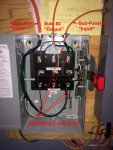
To this end, the six 120v circuits "terminate" in a mini-load center -- labeled sub-panel #2. Sub-panel #2 is 120v -- both legs have been jumped. Power to sub-panel #2 from the utility "originates" from sub-panel #1 and that circuit is protected by a 30 amp (single pole) breaker. This 30 amp feed from sub-panel #1 terminates at a 3-pole, double throw (break-before-make) transfer switch as pictured.
Similarly, power to sub-panel #2 from the generator terminates at the transfer switch as well. Because it is intended to switch all three conductors, all three (hot, neutral and grounding) are insulated within the transfer switch. The body of the transfer switch is "bonded" to the grounding conductors (either that associated with sub-panel #1 or the generator) when it is switched to either the sub-panel #1 or the generator. However, if the transfer switch is in the off position, the body of the transfer switch is not "bonded" -- I'm not sure is that might pose a NEC problem.
The portable generator in this case is a Honda EU2000i. As manufactured, the frame of the generator and all other not-intended-to-conduct-current parts are NOT connected to the generator's neutral conductors according to the manual. I intend to use a "bonding plug" (a plug with white to bare/green jumped which is plugged into unused outlet on generator), or otherwise bond the generator's neutral to it's grounding lug, to correct this situation by which the neutral will be connected to generator's grounding conductor. The "bonding" of the generator's neutral to the generator's grounding conductor will only occur at the generator and not at the transfer switch or any other location to ensure that there are no "parallel paths".
Inasmuch as the the neutral will be switched at the transfer switch (in addition to the hot and the grounding conductor), and thus the main panel's grounding circuit including its grounding electrode will be unconnected to the generator's neutral thus making the generator a "separately derived system", a separate grounding electrode (10 ft copper rod) will be installed at the location of the generator and connected to the grounding lug of the generator.
Anyone see any issues with above? My, albeit layman's, sense is that it's all good except possibly perhaps for the fact that the body of the transfer switch is not "bonded" when in the off position?
My goal is to connect a small portable generator to the house to power up to 6 120v circuits such that the generator conductors (the hot (black), the neutral (white) and the grounding conductor (bare or green)) are kept entirely separate from the conductors associated with the electrical utility (both hot leads, the neutral, and the grounding circuit and its grounding electrode (10 ft copper rod)).
To this end, the six 120v circuits "terminate" in a mini-load center -- labeled sub-panel #2. Sub-panel #2 is 120v -- both legs have been jumped. Power to sub-panel #2 from the utility "originates" from sub-panel #1 and that circuit is protected by a 30 amp (single pole) breaker. This 30 amp feed from sub-panel #1 terminates at a 3-pole, double throw (break-before-make) transfer switch as pictured.
Similarly, power to sub-panel #2 from the generator terminates at the transfer switch as well. Because it is intended to switch all three conductors, all three (hot, neutral and grounding) are insulated within the transfer switch. The body of the transfer switch is "bonded" to the grounding conductors (either that associated with sub-panel #1 or the generator) when it is switched to either the sub-panel #1 or the generator. However, if the transfer switch is in the off position, the body of the transfer switch is not "bonded" -- I'm not sure is that might pose a NEC problem.
The portable generator in this case is a Honda EU2000i. As manufactured, the frame of the generator and all other not-intended-to-conduct-current parts are NOT connected to the generator's neutral conductors according to the manual. I intend to use a "bonding plug" (a plug with white to bare/green jumped which is plugged into unused outlet on generator), or otherwise bond the generator's neutral to it's grounding lug, to correct this situation by which the neutral will be connected to generator's grounding conductor. The "bonding" of the generator's neutral to the generator's grounding conductor will only occur at the generator and not at the transfer switch or any other location to ensure that there are no "parallel paths".
Inasmuch as the the neutral will be switched at the transfer switch (in addition to the hot and the grounding conductor), and thus the main panel's grounding circuit including its grounding electrode will be unconnected to the generator's neutral thus making the generator a "separately derived system", a separate grounding electrode (10 ft copper rod) will be installed at the location of the generator and connected to the grounding lug of the generator.
Anyone see any issues with above? My, albeit layman's, sense is that it's all good except possibly perhaps for the fact that the body of the transfer switch is not "bonded" when in the off position?