2 phase panel

Status
Not open for further replies.

GG

Senior Member
Location
Ft.Worth, T.X.
1) If you have a 3 phase 120/208V service and you feed a sub panel with legs A and B would that sub panel be considered a 2 phase panel? I always referred to these sub panels as single phase but now I'm thinking they are actually 2 phase because you are using 2 phases from the utility and not 1. 2) Would only taking 2 of the 3 hots to a sub panel create a larger electromagnetic field than if you took all 3 hot conductors to the subpanel?
 
Re: 2 phase panel

The really fast answer is:

No.

Taking two arbitrary phases (say, A and C) is not two phase just because you are only using two out of three phases.

What really happens is that one phase will be considered a reference. Say it's A phase. Now A phase is assigned the arbitrary value of 0. Your gonna need something to measure everthing else against. So we'll use A phase, and we'll call it our reference. It's really only zero when measured against itself. But that's still important.

Now when you measure the C phase against your reference (A phase), (aside from the voltages being different), you see exactly the same thing you'd see if:

[A] You measured either leg against neutral on a single phase system.

You measure one leg against the other on a single phase system.

Ed MacLaren has many good images he's posted in the past to describe this better. I haven't seen any posts from him in a while. Hope he's ok.

There is something that really is two phase but it's unlikely most of us will need to deal with it. It's two single phase supplies 90? out of phase with each other. that's very different though.

It's easier to see using images of the wave forms.

Edit: You know what I think? Like too many things. The whole concept just isn't described very well by what it's called. Any intelligent person would be confused by single phase having two phases against neutral (or is that one phase against neutral, that's just a retorical question designed to antagonise anyone who thinks it can't be described better) being called single phase while three phase has three phases against neutral (if there's a neutral. Even if you take the neutral away you still have three and two.

Always the language we use is the last thing to be fixed. And the reason, because it's so old. You'd think that would be the reason we should fix it.

[ June 10, 2005, 07:04 AM: Message edited by: physis ]
 
Re: 2 phase panel

Here's what the differences are, between a 2? and a 3?, 6?, or 9? Systems' Transformer connection scheme:

-----------------------------------
PART 1: 2? (2 Phase) Systems
-----------------------------------

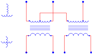
2phd1.gif


Fig. 1a: 2? Transformer Connection Scheme #1;
2? 3 Wire "Tee" Primary x 2? 4 Wire Secondary.

----------------------------------------------
----------------------------------------------

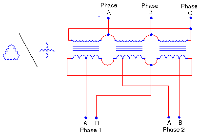
2ph_detail3.gif


Fig. 1b: 2? Transformer Connection Scheme #2;
3? 3 Wire Delta Primary x 2? 4 Wire (Taylor) Secondary.

------------------------------------------------
------------------------------------------------

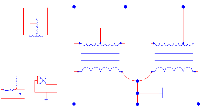
2phd2.gif


Fig. 1c: 2? Transformer Connection Scheme #3;
2? 3 Wire "Tee" Primary x 2? 3 Wire "Vee" Secondary.

------------------------------------------------
------------------------------------------------

Link for details to the 2 Phase Schematics:

2 Phase Transformer Schematics

-----------------------------------------------
-----------------------------------------------

-----------------------------------------
PART 2: 3? (3 Phase) Delta Systems
-----------------------------------------

deltad3.gif


Fig. 2a: 3? Delta Transformer Connection Scheme #1;
3? 3 Wire Delta Secondary.

------------------------------------------------
------------------------------------------------

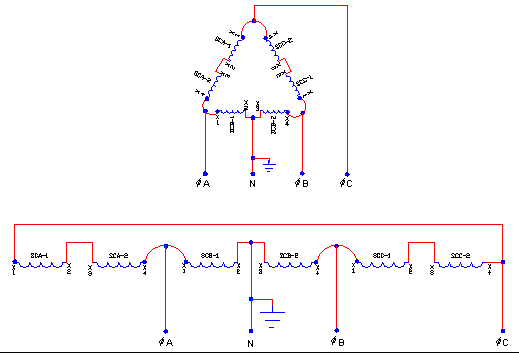
delta_detail1.gif


Fig. 2b: 3? Delta Transformer Connection Scheme #2;
3? 4 Wire Delta Secondary.

------------------------------------------------
------------------------------------------------

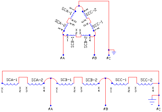
deltad2.gif


Fig. 2c: 3? Delta Transformer Connection Scheme #3;
3? 4 Wire Open Delta "Vee" Secondary

------------------------------------------------
------------------------------------------------

Link for details to the 3 Phase Delta Schematics:

3 Phase Delta Transformer Schematics


------------------------------------------------
------------------------------------------------

-----------------------------------------
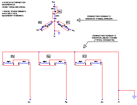
PART 3: 3? (3 Phase) Wye Systems
-----------------------------------------

wye_detail1.gif


Fig. 3a: 3? Wye Transformer Connection Scheme;
3? 4 Wire Wye Secondary.

------------------------------------------------
------------------------------------------------

Link for details to the 3 Phase Wye Schematics:

3 Phase Wye Transformer Schematic


------------------------------------------------
------------------------------------------------

-----------------------------------------
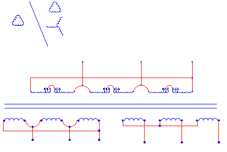
PART 4: 6? & 9? Systems
-----------------------------------------

6ph_detail.gif


Fig. 4a: 6? Transformer Connection Scheme;
3? 3 Wire Delta Primary x 6? (3 Wire Delta + 3 Wire Wye) Secondary

------------------------------------------------
------------------------------------------------

Fig. 4b: 9? Transformer Connection Scheme;
3? 3 Wire Delta Primary x 9? (3 Wire Delta + 3 Wire Wye + 3 Wire Wye) Secondary

***NOTE***

"Fig. 4b 9? Transformer Schematic exceeded maximum images per post (max is 8 images). To view this drawing, please use the link below.

------------------------------------------------
------------------------------------------------

Link for details to the 6 & 9 Phase Schematics:

6 and 9 Phase Transformer Schematics


Scott35

edited duew teu sphelleeng airrors (edited, due to spelling errors) ... D'OHH

[ June 13, 2005, 09:24 PM: Message edited by: scott thompson ]
 
Re: 2 phase panel

Using 2 hot wires and a neutral of a 4-wire wye system to feed a panel is more properly called a network or V-phase feeder. Calling it a 2-phase can cause confusion. A network panel is NOT single phase and I have used 2 stepup transformers to connect a 3 HP 480 volt 3-phase motor to a 120/208 volt network panel.

I have worked in a foundry where 2 of the induction melters ( for aluminum ) used 4-wire 2 phase power derived from 480 volt 3-wire 3-phase power using dedicated Scott connected transformers. 2-phase power that has a 90 degree phase difference between phases is far from obsolete. There are still some specialized uses.

Another way to get 2-phase power from say 277Y480 volts would be to use a 480 volt primary single phase transformer and a 277 volt primary single phase transformer. Not the most efficient way but they are stock transformers. Also, in a Scott Connected transformer the center tapped winding on the 3-phase side has more KVA in it than the 2-phase side of that transformer.
 
Re: 2 phase panel

Originally posted by mc5w:
Another way to get 2-phase power from say 277Y480 volts would be to use a 480 volt primary single phase transformer and a 277 volt primary single phase transformer.
There is no way to get 2-phase from a 3 phase system through the use of transformers.

2 - phase is as much a different system from 3 phase as 6 - phase would be.

It is dependent on the generator, not the transformers.
 
Re: 2 phase panel

Originally posted by iwire: There is no way to get 2-phase from a 3 phase system through the use of transformers.
True. And the simple reason is that 3-phase quantities (i.e., voltages and currents) are separated from each other by 120 degrees of phase angle, and that 2-phase quantities are separated from each other by 90 degrees of phase angle.
 
Re: 2 phase panel

Charlie B and Iwire,

I beg to differ with you. One method, already mentioned, is the "Scott connection". The secret to this is that other phase angles can be obtained from various taps on the transformer. That is, a voltage divider also divides phase.

Look it up.

Rattus

[ June 13, 2005, 11:24 AM: Message edited by: rattus ]
 
Re: 2 phase panel

A "T" connected transformer arrangement provides a three phase output from a three phase input. The T connection uses two transformers and both the primary and secondary are connected in tee.

A "Scott" connection provides a two phase output from a three phase input. The Scott connection uses two transformers also, but only the primary is tee connected, the two secondary windings are not interconnected at all. Sometimes this is called a Scott Tee connection but that term can be confusing.

A "Taylor" connection is one of several methods providing a three phase to two phase conversion, by using three transformers. The Taylor connection has a delta primary and a "kind of delta" secondary with somewhat special tap arrangements.

edited: typos

[ June 13, 2005, 01:53 PM: Message edited by: jim dungar ]
 
Re: 2 phase panel

Originally posted by rattus:
Iwire,

I beg to differ with you. One method, already mentioned, is the "Scott connection". The secret to this is that other phase angles can be obtained from various taps on the transformer. That is, a voltage divider also divides phase.

Look it up.
OK I can eat crow. :)
 
Re: 2 phase panel

That's ok Bob, I made a mistake once--thought I was wrong.

Think of it this way:

It is not the transformers per se, it is the voltage divider property of a tapped inductor.

Draw the phase diagram for a 4 wire wye.

Now superimpose the schematic diagram of a delta load on the phase diagram.

Now draw a fourth vector at 90 degrees to one of the wye vectors.

The intersection of this vector with the load element indicates the tap position which will provide a 90 degree phase angle. I think it is 87% from one end.

This load element could be a variable autotransformer. You could obtain phases over a range of 120 degrees.

Rattus
 
Re: 2 phase panel

Bob, for an easier understanding do this:

On paper, connect the outer terminals of a potentiometer to any two phase voltages. As you turn the pot, the wiper voltage relative to neutral changes, and so does the phase. This is obvious when the pot is in the fully CCW and CW positions.

[ June 14, 2005, 12:21 AM: Message edited by: rattus ]
 
Status
Not open for further replies.
Top