synchro
Senior Member
- Location
- Chicago, IL
- Occupation
- EE
...
I need to think more about how the different phase angles of the rectification pulses play with the phase shift of these _series_ primary coils. You can't have current flowing in a 'left' phase without current flowing at the same time in corresponding 'right' phase, and vice-versa.
-Jonathan
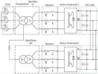
Perhaps the rectification is being done synchronously with PWM using an "active front end". That way the two rectifier circuits having drive voltages 30 degrees apart can be drawing current at the same time, unlike with diode based 12-pulse rectifiers.
An example is in the picture below: