- Location
- New Jersey
- Occupation
- Journeyman Electrician
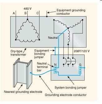
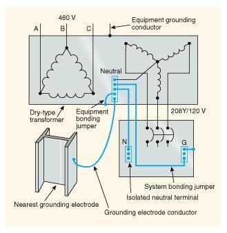
Has anyone looked at the illustration (Exhibit 250.13) for Article 250.30? IMO the illustration labeled Exhibit 250.13 is incorrect. It seems that the terms "Equipment bonding jumper and System bonding jumper" are switched. Or am I reading this incorrectly?